(This article is re-formatted from the following publication:
Mustacich, R. 2014. Freak or Fake? A New Fingerprinting Method for Distinguishing between
Original and Fraudulent Extra Perforations of 19th Century
Revenue Stamps. The American Revenuer, 67(1): 2-19.)
Freak or Fake? A New Fingerprinting Method for Distinguishing between Original and Fraudulent Extra Perforations of 19th Century Revenue Stamps
By Robert Mustacich
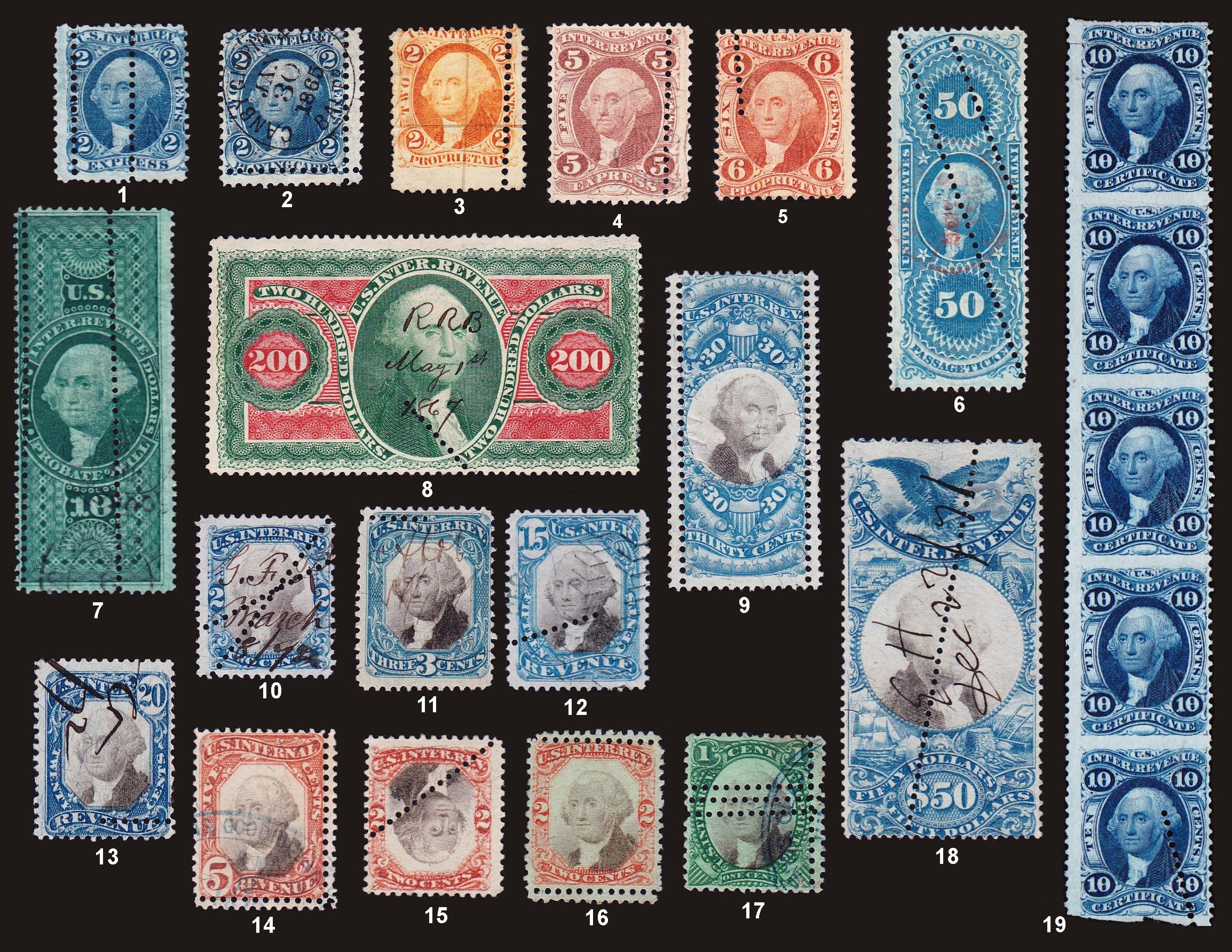
Figure 1. Nine of these stamps have genuine extra perforations, and the rest are forgeries. Can you pick out the correct nine stamps? See the end of the article for the answers.
Stamp experts have long suspected that extra perforations appearing on 19th century revenue stamps might be fraudulent. Dealers and collectors alike would benefit from an accurate way to assess these stamps, but thus far no definitive method has existed. Being curious about this topic, I devised a new method, using high-resolution digital scans coupled with computer-based analysis that distinguishes certain extra perforations. This precision method is able to create a unique “fingerprint” for each perforation and detect which type of perforating machine was used – either rotary or stroke – which is key in revealing forgeries. Most surprisingly, it gives strong evidence that most of the forgeries could have been done by a single perpetrator.
Conventional stamp wisdom has held that perforations crossing the interior of the stamp (for example, #18 in Figure 1) are forgeries, while those near and parallel to the edge (often called “double perforations,” see #3 in Figure 1) are genuine, especially for the First Issue revenue stamps. However, I have found this rule-of-thumb to be somewhat unreliable. Can you spot which stamps in Figure 1 are “freaks,” or errors in production, and which are “fakes”? According to my findings, half of the stamps in Figure 1 have extra original perforations, but you might be surprised by which ones they are. The other half contain fraudulent perforations, added to mimic errors in original production in order to raise the value of the stamp. Answers are given at the end of the article.
The Smoking Gun
Detecting forgeries is closely linked to knowing how the genuine article is made. In the 19th century, original perforations were done by a rotary perforator. Presumably, the few rotary perforators in the U.S. were in the control of the government or its contractors, and consequently would not have been available to forgers. After printing, a sheet of stamps traveled between a row of wheels, each with 192 pins (Leavy, 1918), and a row of wheels with closely matching holes, creating the familiar part-perf stamps. A second pass through a perforator with the sheet turned 90 degrees completed the perforation of the sheet. Infrequently, a sheet would become crooked or be run twice, resulting in extra original perforations. The rotary perforator was a complex machine for the era, and was very difficult to fabricate. It is not surprising that a new high-resolution method reveals myriad tiny inconsistencies in the resulting perforations.
An alternative perforation device, presumed to have been used in forgery, is called a stroke perforator. Though scarcely documented, it is assumed to have been a small device with a single row of pins in a lever-operated punch. This device, like the rotary perforator, creates a perforation row with many microscopic inconsistencies. Detecting the use of a stroke perforator would be the smoking gun which would reveal a forgery.
The logical way to detect extra lines of perforation added by a forger would be to compare these with the original edge perforations on a given stamp. (In this article I will use the terms “original” and “added” to distinguish between genuine and fraudulent perforations.) I started by overlaying images of different perforation rows from the same stamp using software such as Adobe Photoshop. However, the more stamps I looked at, the less conclusive the analysis became. Next I tried more detailed analysis of the gauge using digital images. I did indeed find variations, not only between the edges and the extra lines, but also among the four edges of the same stamp. I quickly discovered so much variation in perforation gauge that the approach collapsed. This confirmed the observation of Brett (1990) that perforation gauge did not appear to be useful for analyzing extra perforations.
I decided that this problem called for even more powerful digital technology and analysis. Drawing on my background as a research scientist, I designed a complex method using a high-resolution digital scanner and various pieces of software which I wrote for the project. Finally, at this level, some remarkably distinctive patterns started to emerge distinguishing between rotary and stroke perforations. Using this approach, a perforation row now revealed a unique “fingerprint” comprised of such features as spacing, placement, hole size, and hole shape.
Matching Fingerprints
Under high magnification, each wheel of a rotary perforator produces a characteristic repeating “pattern” that is 192 pins – or holes – long. The pattern is nearly 13 inches in length, and each wheel has its own pattern. When I analyzed the four edges of any given stamp, each edge consistently had a different “fingerprint,” defined as a the distance between hole centers as a function of pin position, as a result of all of the different wheel and pin possibilities. A rotary perforator operating with 18 wheels would have more than 3400 individual pins! In Figure 2, these “fingerprints” for the edges of a stamp are represented in the graph at the top left. Each black line represents the pattern of one edge of the stamp, and even the untrained eye can see that there is no duplication between them.
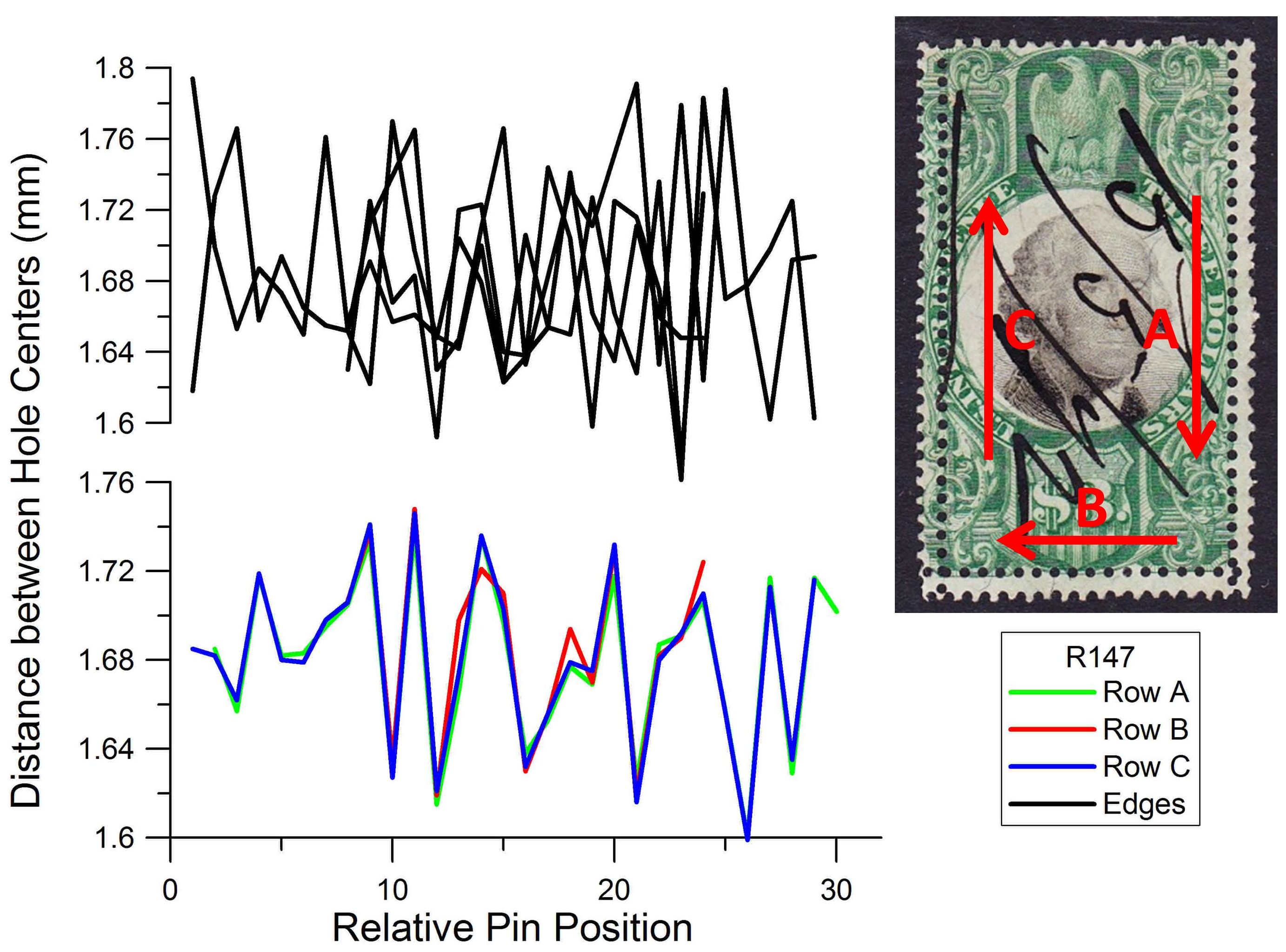
Figure 2. Comparison of perforation pattern “fingerprints” on a Scott #R147. The upper plot compares the four edge perforation rows, which show no similarity to one another. The lower plot compares the three extra lines of perforation, which are nearly identical, a very strong indication of forgery. The fingerprint directions show that the stamp was turned about its center and punched near each edge.
In contrast, while examining the suspicious extra rows of perforations, I was amazed to see a very different result on a single stamp -- each extra row had a nearly identical fingerprint! To make sense of this, consider how a forger would use a stroke perforator. A single stamp could be punched, carefully rotated, and then punched again; it’s easy to imagine that the same section of pins would be used for both lines. The colored graph in Figure 2 is a stunning example of this technique. This graph shows a near-perfect match in the fingerprints of the three extra lines of perforation (Rows A, B, and C). This duplication even shows that the stamp was rotated in place for punching the three extra rows. Such a result is not possible with a rotary perforator.
Figure 3 shows an example of the often-observed extra perforations intersecting at odd angles. In the 4¢ inland exchange stamp pictured in Figure 3 (Scott #R20), there are no matching patterns found among any of the edges. However, the patterns of the extra perforations show a close match, evidence of a stroke perforator. (Incidentally, the missing extra perforation hole at the right edge of the horizontal row is evidence that the extra perforation was added after the stamp was separated from the sheet; close examination shows that the edge of the stamp was folded rather than having the last hole punched – something that would not occur if the stamp was part of the original sheet.)
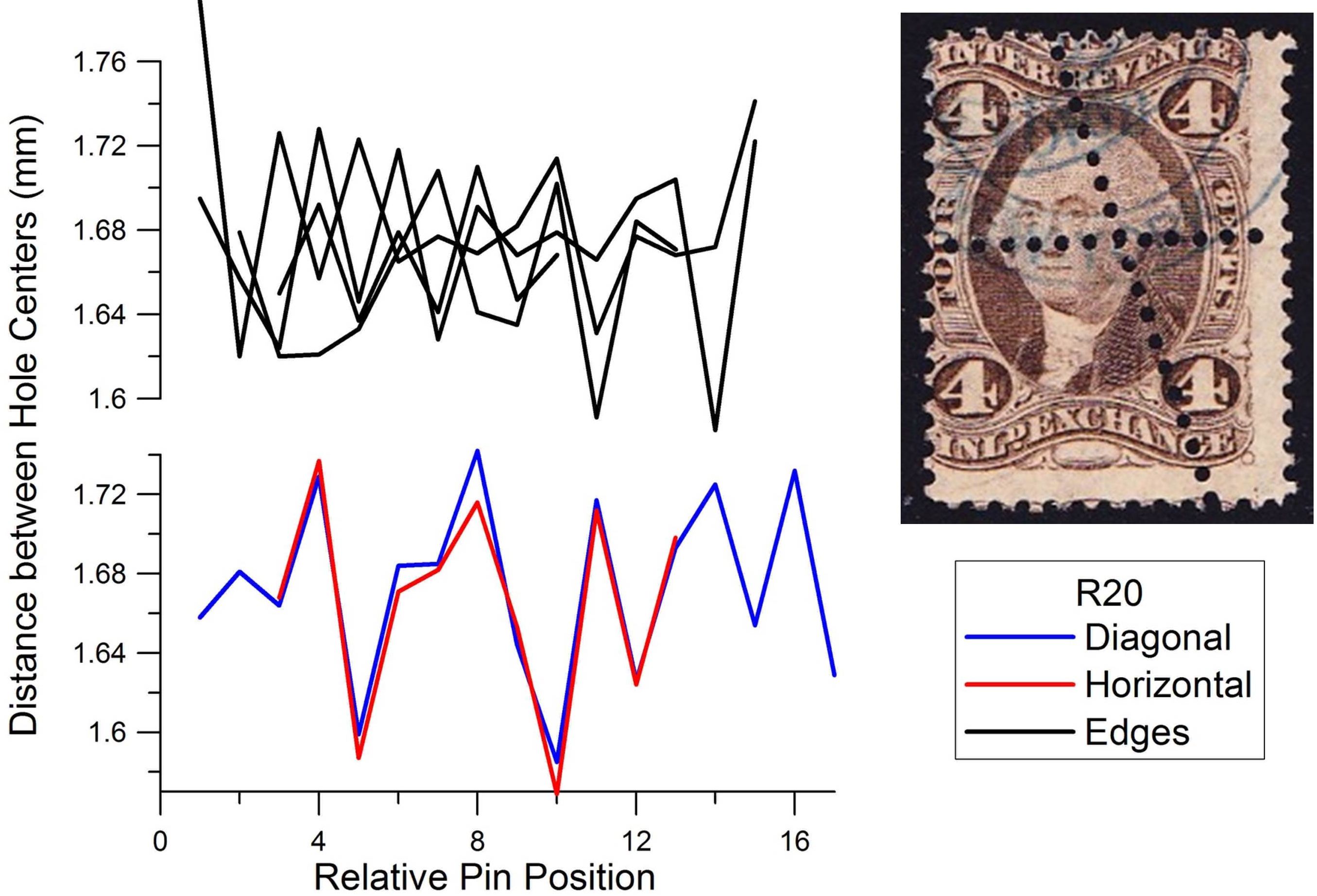
Figure 3. Analysis of perforation patterns for Scott #R20, which contains interior crossing rows. These fraudulent rows match strongly in pattern, while the edge perforations show no correlation to one another.
Figure 4 shows an example typical of multiple added perforations, some parallel but separated from each other. In this example on the $10 third issue stamp (Scott #R149), the two vertical rows of perforations match each other without any shift in alignment. This shows that the two parallel rows were made in this case by carefully moving the stamp slightly in a direction perpendicular to the pins. The centered alignment of the horizontal row’s pattern match again suggests that the stamp was approximately rotated on center for this perforation.
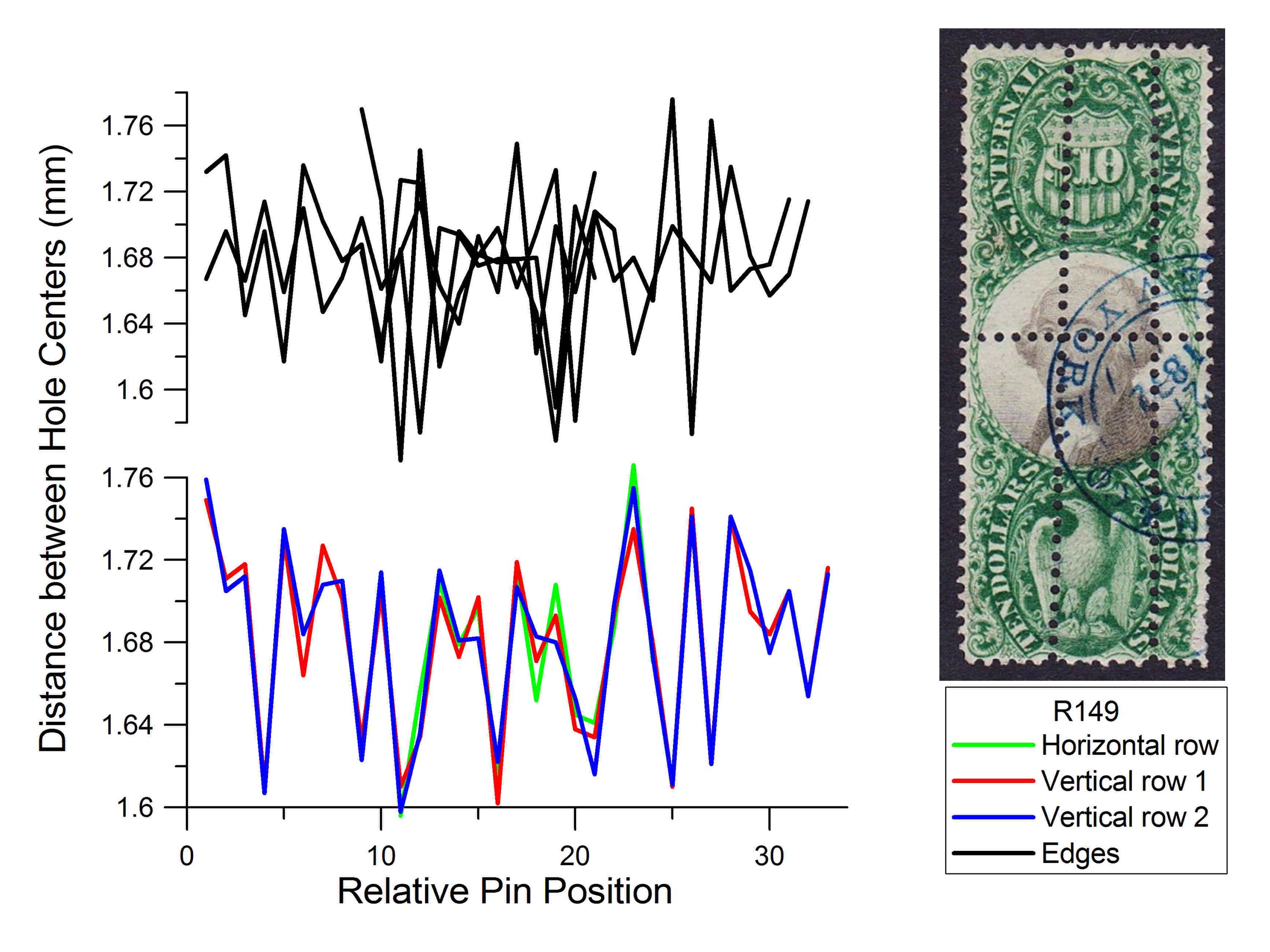
Figure 4. Analysis of Scott #R149, with fraudulent extra perforations. The two parallel vertical rows of extra perforation exhibit no shift in pattern, which would be accomplished by carefully advancing the stamp by hand in a stroke perforator.
An example of a closely spaced pair of added perforations spanning the center of the stamp is shown in Figure 5 for the second issue $1.30 stamp (Scott #R119). Note the near perfect matching of the hole spacing sequences. Again, there is no apparent alignment shift between the two vertical rows, indicating that the stamp was carefully moved a small distance in the stroke perforator, perpendicular to the pins, to punch the next row of holes. Offset a little to one side, the stamp appears to be approximately turned about center to create the horizontal row near the top of the stamp. While the top row has the appearance of a possibly original extra perforation (often called a “double” perforation error), it is an added perforation because of its pattern match to the other perforations.
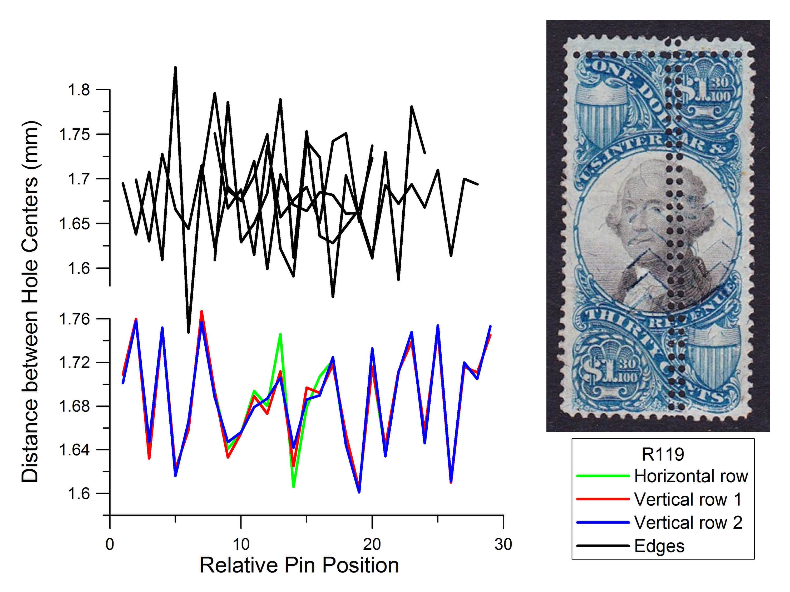
Figure 5. Analysis of Scott #R119. This stamp, like Figure 4, contains two extra vertical rows with identical patterns, clear evidence of forgery: Such a close pattern match would be impossible using a rotary perforator.
In contrast to the examples in Figures 2-5, Figure 6 shows a typical example of genuine extra perforations and the lack of correlation between them (Scott #R113). Just as with the edges, there is no apparent shared pattern between these extra rotary perforations.
These results agree with the earlier studies of these stamps, summarized by Brett (1990) in an article including an annotated bibliography. This survey was supplemented with new findings of these stamps on document (Mahler 1991a,b,c). Mahler (1991c) summarized a general view of these stamps in the form of three hypotheses: 1) perforations spanning the stamp interiors are almost always fraudulent; 2) original diagonal perforation errors are usually found on stamps issued or used in 1863 or earlier; and 3) the original perforation errors reached the public due to the extraordinary pressure on the printers during early production to fill orders for these stamps. Brett considered the added perforations to be produced by a stroke perforator based on observed repetition of distinctive features in parallel rows such as missing punched holes (i.e., so-called “blind” perforations). Further considerations suggested to him that the added perforations were punched after the use of the stamps.
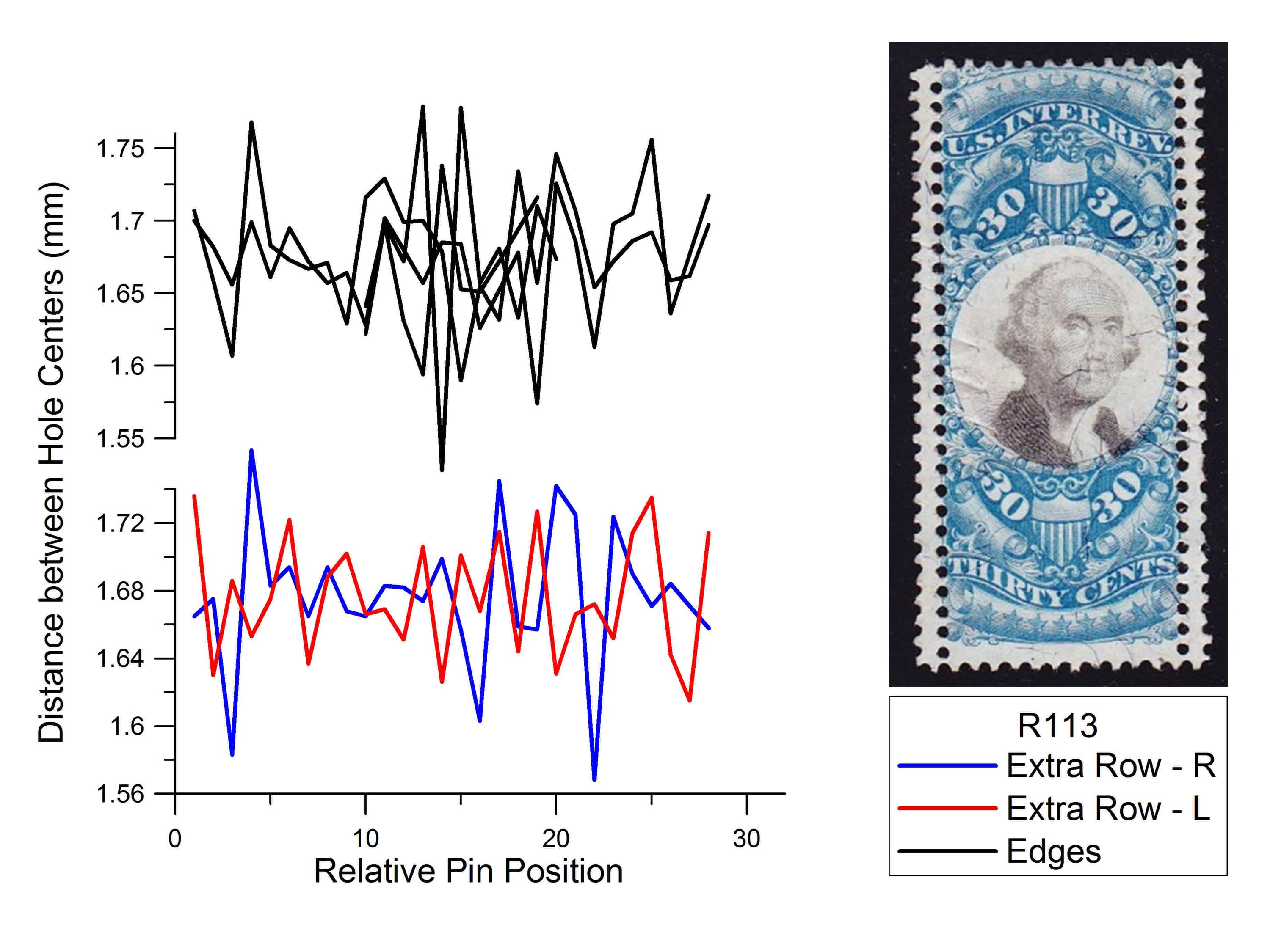
Figure 6. Analysis of Scott #R113. Unlike the previous four examples, this stamp exhibits genuine extra perforations. Like the edge perforation rows, these extra rows show no matching of the perforation fingerprints.
So if a stamp contains multiple extra rows of perforation, and these result in nearly identical “fingerprints” under my analysis, I could conclude that these were made by a forger using a stroke perforator. But what if the stamp has only one additional row of extra perforations? Are there some distinguishing characteristics of stroke perforations? Further study revealed that yes, there are detectable micro-features such as the shape of holes and their size. The latter can frequently be detected with a specialist perforation gauge; this is discussed in a later section of this article. However, an even more reliable test is to compare the fingerprint of a single row to known stroke perforations on other stamps. A match between these is certain proof of forgery. Thus for any given row of perforation, I could now determine its origin as fraudulent or authentic in nature .
Family Relations
Each stamp that I scanned and analyzed was added to a database of digital “fingerprints.” As this database grew larger, it provided ever-increasing opportunities for fingerprint matching. The results were overwhelming. Any row of added perforations had a pattern closely matching that of other added rows, forming a network which will be called the Added Group. It would be as if a group of people were found to be all related, anywhere from identical twins to cousins. In contrast, if an original, genuine perforation was submitted for matches, it failed to significantly match anything in the Added Group, and showed only slight similarity to other original perforations.
The close similarities within the Added Group strongly suggest that these forgeries were done on a very limited number of stroke perforators, possibly even one, which is not a new idea. Nast (1908) extensively commented more than 100 years ago on these stamps. He believed that they became numerous in the years following an effort by Edward B. Sterling, a prominent revenue dealer and specialist, to include these curiosities (catalogued at premium values) in his “great catalog of 1888,” namely Sterling’s Standard Descriptive and Price Catalogue of the Revenue Stamps of the United States (see Appendix II for a discussion of this catalogue in light of this study). Brett (1990) further references that, according to the recollections of Hugh Barr, a New York philatelic auctioneer, “These fakes began to appear about 1890 and it is understood that most of them, if not all, came from one source, a stamp dealer quite active in New York, who had acquired a perforating machine, and who was already a suspect in connection with many other forms of fakery, such as the altering of stamps and the affixing of stamps to covers, quite a nefarious character.” A dealer in New York was also reported to have a stock book completely filled with these curiosities while debate raged whether they were “freaks” or “fakes.”
Although in general my findings support the views of Brett, I also uncovered numerous exceptions. My research shows that some perforations extending into or through the stamp interiors are original, products of rotary perforation. Similarly, there are rows which look like original perforation errors (sometimes called “double perforations”) that were actually punched with a stroke perforator. Rather than calling these stamps “interior” and “double” perforations, respectively, and then having to call out many exceptions, I am instead classifying these extra rows as “original” genuine perforations produced by a rotary perforator, or “added” fake perforations produced by a stroke perforator. Since the stamp edges are original perforations, these are sometimes referred to as “edge” perforations. There are also many examples of perforation rows which do not extend fully across the stamp. I will refer to these as “partial” rows of perforations in this article.
Technology
A very brief overview of the technology I developed for this investigation is contained in the following paragraph, and the interested reader can find supporting technical details in Appendix III. Basically, a semi-automated method was developed for the detailed analysis of minute perforation features in images. Stamps were placed in a high-resolution optical flat-bed scanner and scanned at 2400 dots per inch (dpi) or higher resolution. Images of individual perforation rows were then manually processed using standard image editing software to reduce the images to edges and delete superfluous information. Custom computer software was written to determine the distances between hole centers, radii of the holes, lateral zig-zag, circularity of the holes, and statistics of these features for the row. Computer programs were also written to seek pattern matches and possible networks of interrelationships between the different perforation rows. The collection of revenue stamps with extra perforations used for this study consists of about 220 stamps covering the first three issues (with the exception only of the “Persian Rugs”) and most of the early Proprietary revenues. This collection provided data for approximately 1,000 perforation rows, including the edge perforations .
A wide range of scan resolutions was tested to determine the optimal resolution of 2400 dpi for analysis of the hole features listed above. Scanning the stamps at greater resolutions was not found to provide any benefit, and increased both the file sizes and computation times considerably. The spatial resolution of the hole centers and radii is actually much greater than the linear scanning resolution (1/2400 inch, or 0.00042 inch) because of the two-dimensional aspect of the mathematical fitting of circles to the images. For typical perforation hole sizes of approximately 1 mm, the effective resolution of the hole center position and radius is estimated to be less than 1 micron, or one thousandth of a mm (0.00004 inch). In a test with a row of perforations, the same row was scanned 10 times while altering the position of the stamp in the scanner between each scan. The average error for each hole radius was merely 0.9 microns, and the average error for each of the center-to-center hole spacings in the row of perforations was only 1.1 microns. This provided ample precision for measuring any of the features for perforation fingerprinting.
It is reasonable to conclude that minute inconsistencies in hole spacing is the most easily measured characteristic since uniform spacing of pins and holes is the most difficult machining challenge in fabricating a perforator, so this feature was used as the basis for my analysis. The other characteristics of hole size and shape show more consistency, probably because the pins would likely be cut from a sufficient length of the same wire stock. Drill sizes are also relatively consistent, so the size of holes in the machine should also be fairly uniform, even if several drill bits are used in order to avoid drill breakage. Surprisingly, the resulting perforation hole size is usually nearly the same size as the pins rather than the size of the machine holes (U.S. Bureau of Engraving and Printing, 2013).
Other sequences of features, such as hole size and measures of circularity, can also be used to create row fingerprints capable of revealing pattern matches, but with diminished accuracy in comparison to using hole spacing. The alignment of the hole size sequence is shown in the lower graph in Figure 7 for the Scott #R147 example discussed in Figure 2. When the sizes are plotted using the same sequence alignments used in Figure 2, matching is still observed, but with less precision than when using hole spacing. Similarly, the sequences of hole fit errors (a measure of the deviation from a circle described and illustrated in Appendix III) only roughly match as shown in the upper graph of Figure 7.
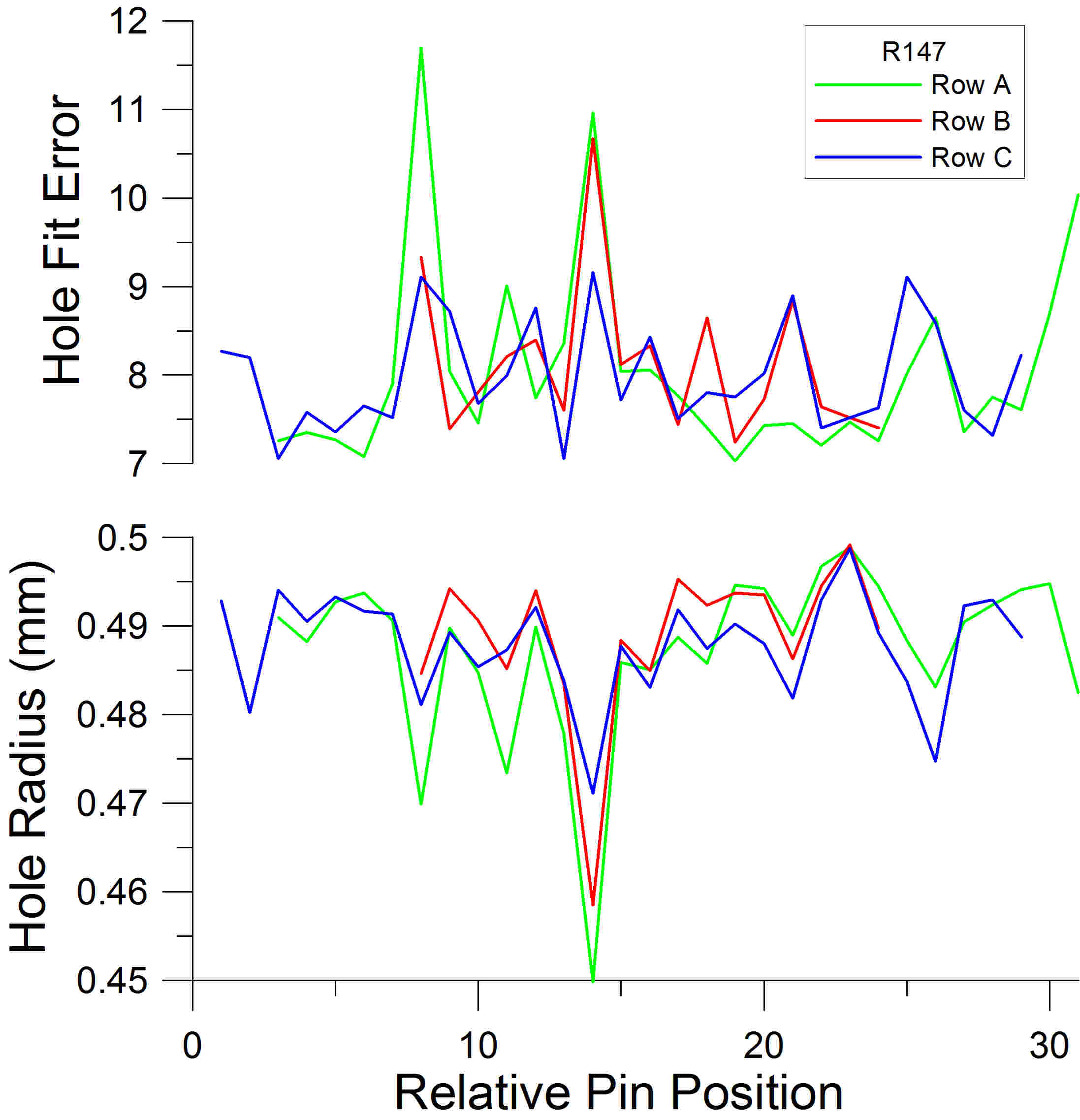
Figure 7. Two more profiles of Scott #R147, as in Figure 2. The upper graph uses hole fit error as the basis for analysis, rather than the spacing between hole centers. The lower one uses hole size. These methods are less precise, although the close similarity of added rows is still apparent.
Clean Cut
Further analysis revealed that the stroke perforator has a smaller average pin radius and also cuts a sharper and more circular hole than the rotary perforator. Each hole was analyzed by comparison
with a perfect circle superimposed on it. This comparison yielded a measurement of the hole radius, and of the “hole fit error,” or amount of deviation from the perfect circle. An interesting qualitative relationship exists between the hole fit error and the hole radius that is peculiar to the added perforations (plotted in Figure 8). The added perforations (red) have average hole fit errors and radius values that lie in an area of the graph that is largely different from the bulk of the data for original extra perforations (green). The separation is quite remarkable considering the significant range of normal variations usually present in these parameters. While the hole fit error reflects a combination of both circularity and smooth edges, these results show that the added perforations typically have a smaller hole radius and hole fit error than the original extra perforations produced by rotary perforators. This is consistent with Brett’s observation that the suspect perforations were generally cleaner cut (Brett, 1990). A simple test can be done with a perforation gauge. Whereas the hole radius of rotary perforation holes is typically larger, the hole radius of the added perforations is approximately equal to or less than the size of the holes illustrated on some U.S. specialist perforation gauges. More specifically, the U.S. specialist gauge pertaining to 19th century revenue stamps is Kiusalas 12-66. The Precision U.S. Specialty Multi-Gauge (Sonic Imagery Labs, 2013) has Kiusalas 12-66 hole sizes which measure approximately 0.488 mm radius (uncorrected for laminate thickness when scanned). As a quick test of authenticity, most original perforations show annular gaps between their larger perforation holes and the black hole image on the transparent gauge when held up to the light, aligned, and closely inspected with a magnifying glass. However, while this test may work for a majority of these stamps, Figure 8 clearly shows that there will be some original extra perforations with radii too close to or less than 0.488 mm for which this simple test would be misleading.
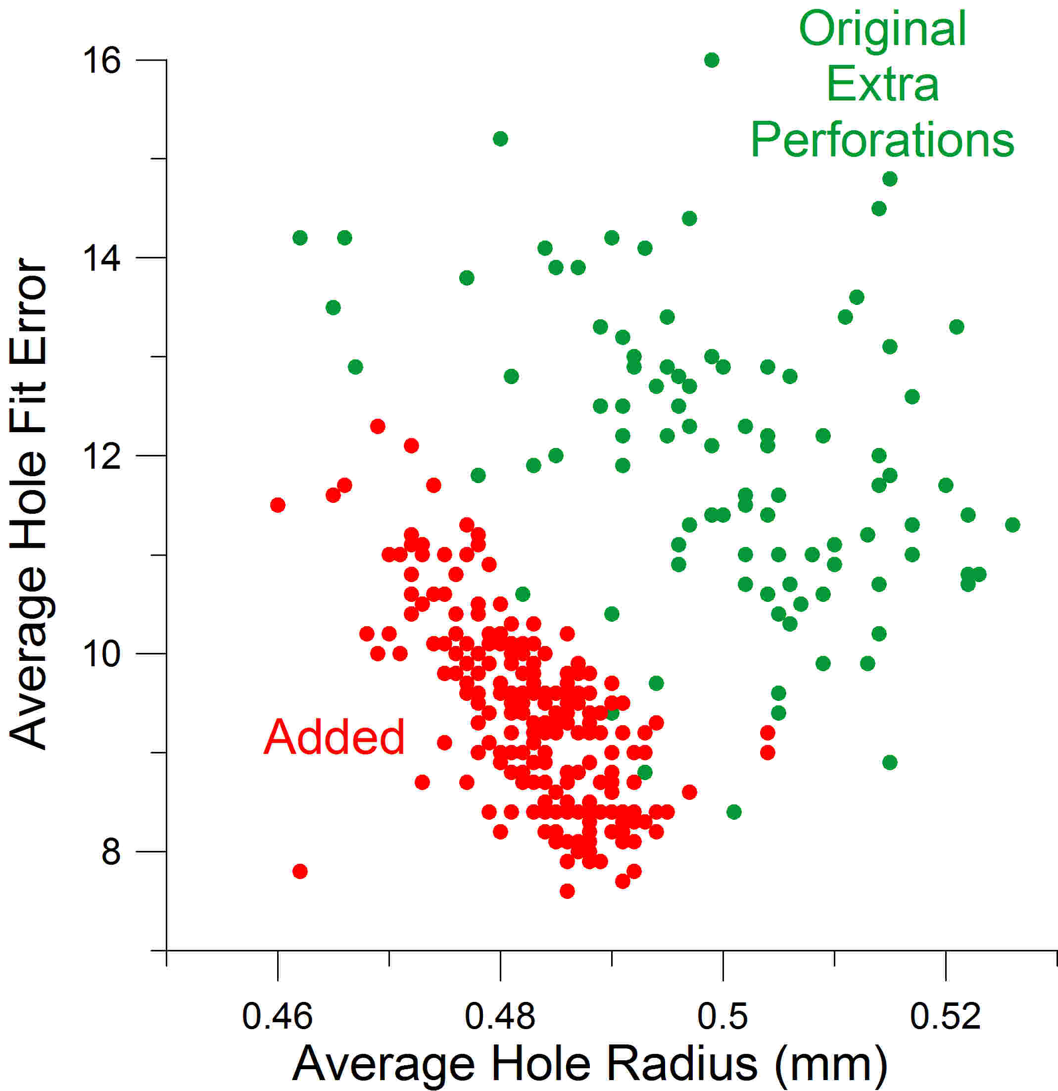
Figure 8. Plot of hole fit error vs. radius, showing a significant difference between the fraudulent added perforations (red) and the original extra perforation errors (green). The “fake” holes are smaller and more sharply cut than the genuine extras, due to the equipment used to make them. This finding is the basis for a simple test using a specialist perforation gauge.
The Bird’s Nest
Comparing the perforation fingerprints from each image looking for the “family relationships” is a good task for a computer—the 1,000 images of perforations rows resulted in 2,000 patterns to consider, because a perforator could conceivably be used in either direction. Also, the scanning of the stamps can be performed in either of two directions by rotating the stamps 180 degrees. For these two reasons, hole spacing sequences in both the forward and backward directions were included in the analysis. To evaluate all possible row pairings for potential fingerprint matches in the collection required an astounding 2,000,000 different comparison studies, each seeking the optimum alignment between a pair of patterns. Each comparison study involves sliding one row past another, one hole at a time. For each possible alignment a correlation score is calculated, and the highest score from all of the alignments is considered the best possible pattern match (the highest correlation). High correlation scores, if found, can then define a network of related patterns, essentially a network of matching or overlapping “fingerprints.”
A network emerged from my computer analysis which showed that virtually every added row of perforation was very similar to many others. When the First Issue images (representing more than half of the collection) are correlated to find pattern, a large and complex network of very strong correlations emerges from the more than 1,000,000 computerized optimizations carried out by the software (see Figure 9). There are hundreds of strong pattern matches that each would be the equivalent of the charts shown in Figure 2-5! These “family relationships” create an intertwined network resembling a bird’s nest. Each row of perforations is represented by a dot. If that row has a strong pattern match to any other perforation row, the dots are connected by a line. The dots and connecting lines were created by NodeXL software (Social Media Research Foundation, 2013). The dots (perforation rows) were grouped by Scott number to the periphery of a ring for better clarity of the network and of fingerprint matches between multiple extra rows on the same stamps. For example, dots representing the extra rows in Figure 3 would be linked by lines to one another as well as to numerous other rows with related fingerprints. A close-up view of these links for Scott number R20 is shown in Figure 10. Since in some cases I have rotated the stamps for scanning individual perforation rows the opposite of how the forger rotated the stamps, the correlation of one row might be with the reverse of my scan of the other row. In this specific case, the horizontal row (the red R20 dot in the center) matches the mirror image of the diagonal row (the purple R20 dot on the right).
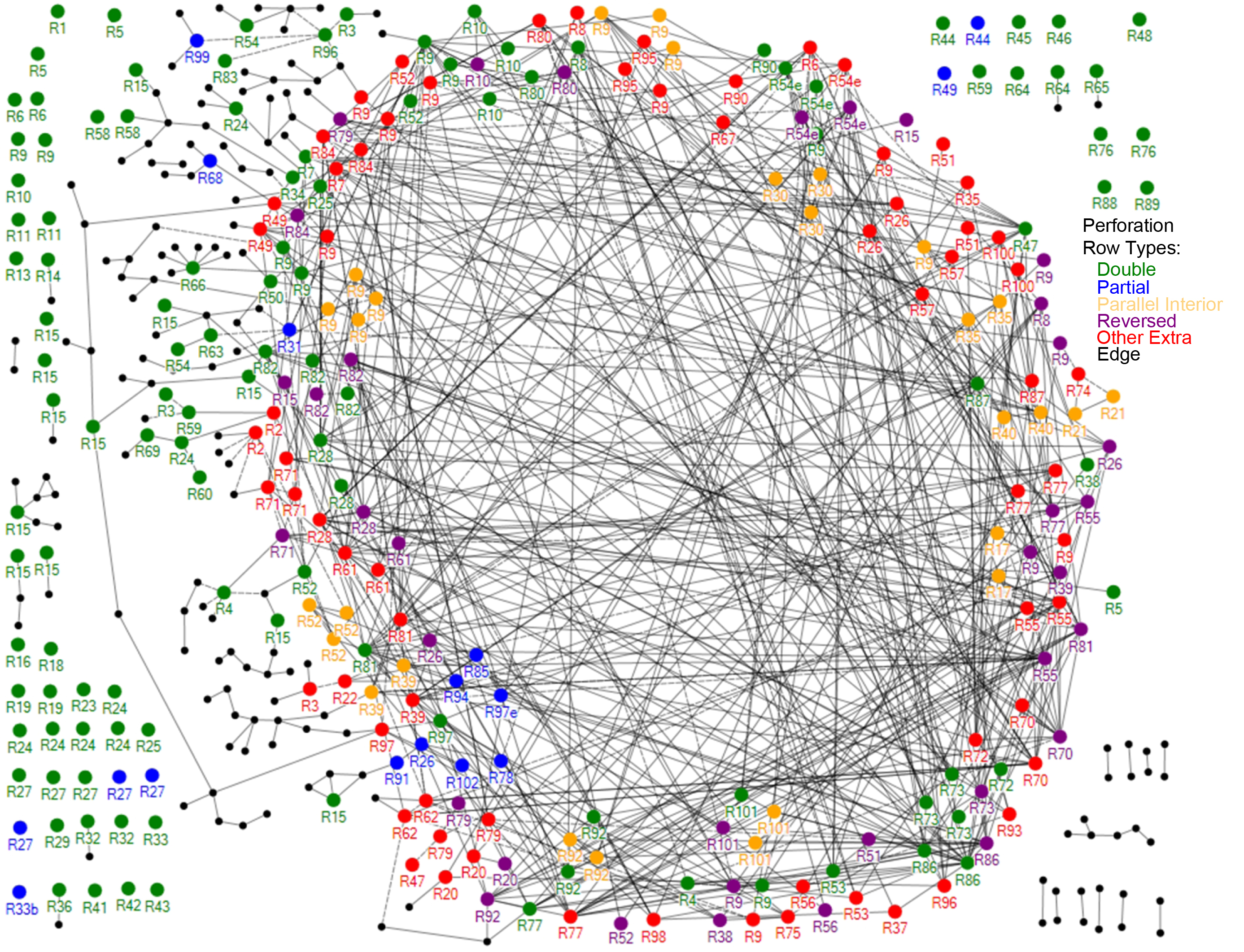
Figure 9. The “Bird’s Nest.” Each dot represents a perforation row, and a line connecting any two shows that their “fingerprints” are very similar. The computer software placed every single “fake” row studied in the first issue revenues in this network, giving strong evidence that they were all done by the same perforator.
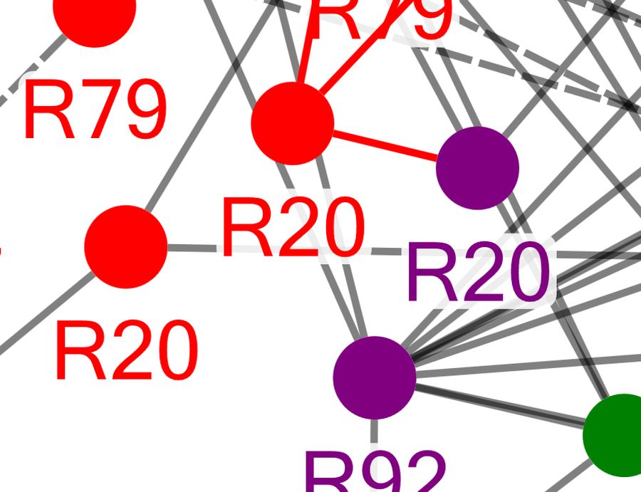
Figure 10. Detail of the “Bird’s Nest.” Each dot is labeled with the Scott number of the stamp on which the row occurs. Strong similarities exist between extra rows on a single stamp, and also between rows on various stamps.
It is obvious from the dense network in Figure 9 that each of the stroke perforations has strong similarities with many others. Amazingly, only a single common network of pattern matches emerges from all of the data. In the figure, the color of each dot indicates the type of perforation it represents (such as interior or partial). It is easy to see that some of the double (green), parallel (orange) and partial (blue) rows are part of the Added Group done by the stroke
Edge perforations (black) and many of the “double perforations” (green) have no pattern matches, or only random infrequent ones, and therefore are not part of this network. (Hundreds of such additional edge perforation patterns were omitted from the chart because they have no pattern matches at all.)
The network of pattern matches between fingerprints from the Second Issue revenue stamps in the collection provides a similar result to the analysis of the First Issue stamps. One notable difference is the much smaller number of genuine double perforations. This is in agreement with the hypothesis put forward by Mahler (1991b) that double perforations are primarily found in the First Issue revenues (of 22 examples he cited on document, 14 were on First Issues, one on a Second Issue, and seven on Third Issues). The 1888 catalogue of Sterling also describes perforation errors consistent with original perforations that continue in diminished numbers in the later revenue issues (see Appendix II). The pattern networks for perforation fingerprints of the Third Issues and the Proprietary revenues of 1871-1881 are very similar to the results with the Second Issues and support identical conclusions. For comparison, the graphical network for the Second Issues is included in Appendix I.
Mirror Images
Interestingly, the pattern matches for the 19th-century revenue stamps form a single dense network regardless of date. This can be observed in two different ways. First, when all of the pattern matches from the entire collection are plotted together, the density of the relationships is independent of whether the different revenue issues are grouped together or not. Second, an analysis can be applied to this data which separates the network into regions of most and least interconnectivity. Strongly interconnected subgroups of fingerprints that are less connected to the other fingerprints will be separated out in this process. I used the Harel-Koren Multiscale procedure (Harel and Koren, 2002) for this analysis. Using this approach, the added perforations sort themselves into two groups. However, one of the two large groups is simply a mirror image of the other one, resulting from all of the reversed fingerprints included in the data set. In essence, there is a single group and no significant subgroups. The dense plot resulting from the Harel-Koren analysis is included in Appendix I.
The Single Perforator Theory
Could a single stroke perforator possibly have produced all of the added perforation patterns? To test this possibility, pattern matches were used to construct a hypothetical row of pins. A computer program started with the closest row matches and worked downward through the network. This process resulted in a pin sequence for a stroke perforator that could produce all of the added perforation patterns. This simulation resulted in a sequence of only 80 pins to punch all of the added perforations in the analyzed collection. 80 pins would constitute a row merely 5 inches long, so this could indeed have been a small, portable device.
The results of this effort are shown in Figure 11, and are presented in order of Scott numbers for simpler reference to the collection. Different copies of the same Scott numbered stamp are indicated by numbers following a “#” sign. The placements of the colored bars show the selection of the pin sequence needed for creating the specific perforation row in the collection. The colors in this chart follow the same color coding used in Figure 9.
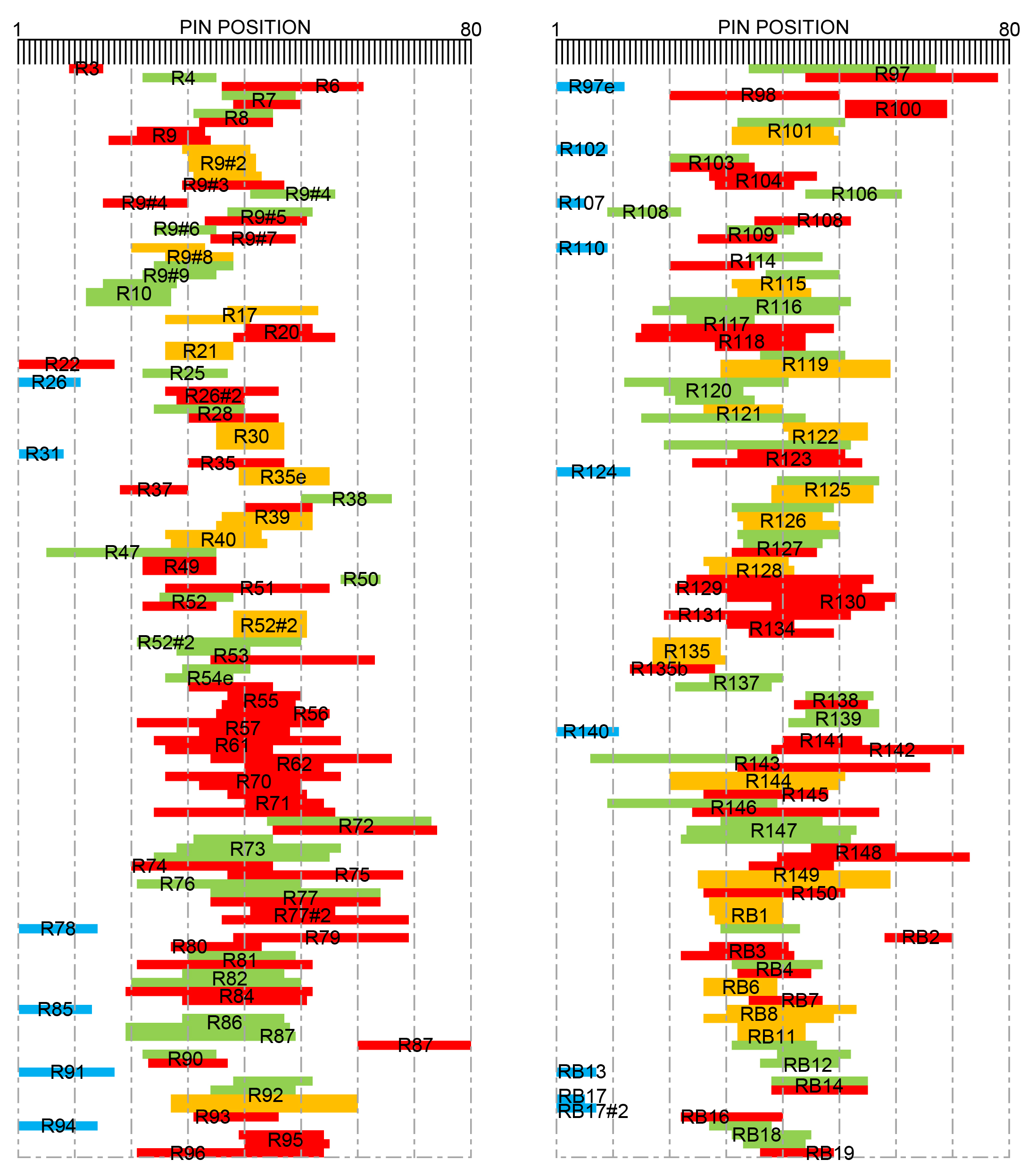
Figure 11. The Hypothetical Stroke Perforator. The computer was able to construct a row of 80 pins, about 5 inches long, which would be able to make every fingerprint pattern in the collection.
It is interesting in Figure 11 that nearly all of the parallel interior perforations that are closely spaced (shown in orange) closely align with each other. This is consistent with these perforation rows being produced by carefully advancing the stamp by hand in the stroke perforator. Also note that there are several triple row examples in the graph (R9#2, R30, R52, R135, and RB1) that are similar to the example having blind perforations in three parallel rows featured by Brett (1990).
The calculated values of the distances between pins are listed in Table 1. As far as accuracy, the average standard deviation of the spacing for all of the aligned sequence data is only 0.016 mm. For reference, this value is less than the 0.02 mm minor unit on the vertical scales of Figures 2-5. The perforation gauge averaging over the nearest nine holes ranges from approximately 11.8 to 12.0 over the length of the 80 pin sequence. This is a small range of variation and a very good match to the Kiusalas 12-66 gauge of these revenue stamps (about 11.9). While some of the longest added perforations in the collection can span around 40 holes, this hypothetical 80-pin pattern is only twice that length, and the results in Figure 11 show an extensive use of or preference for the middle of the pin sequence, at least as created by this computer analysis. While it may be possible to further compact the pin sequence, more data and research would be required to accomplish this. This exercise demonstrates that a relatively short sequence of pins can account for all of the added perforations in the collection.
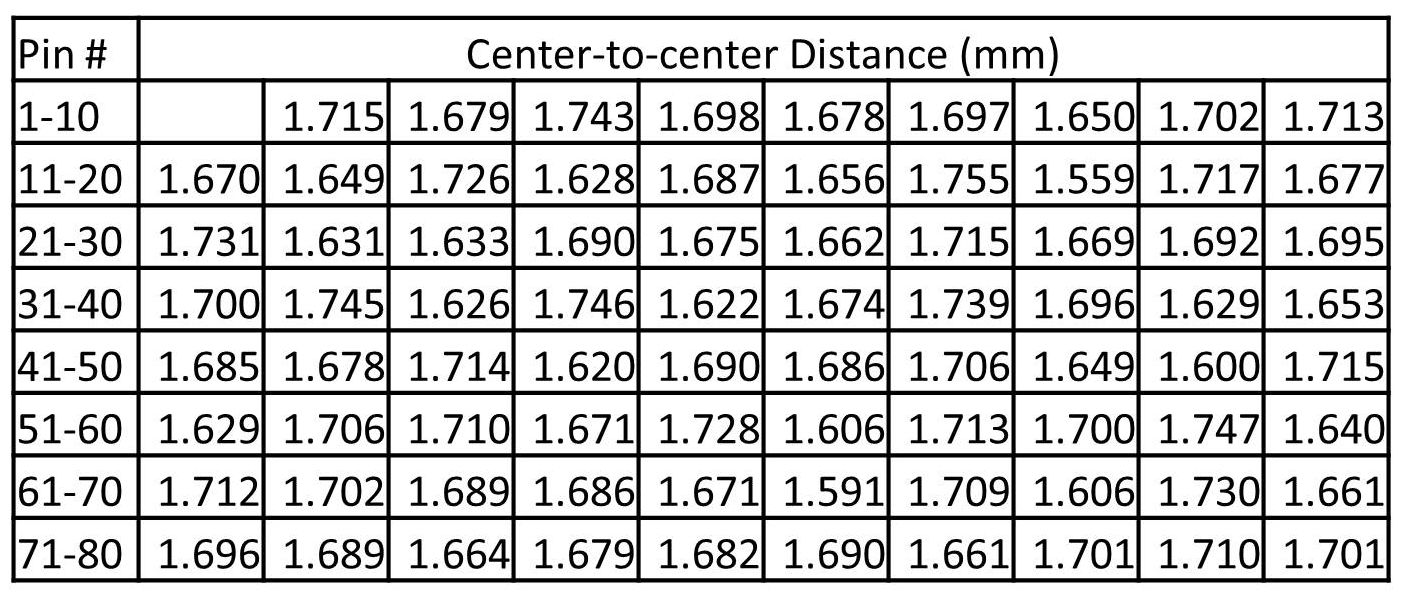
Table 1. Center-to-center pin spacings for a hypothetical 80-pin stroke perforator created by computer analysis of the alignments in the fingerprint matches of added perforations.
It would have been more likely that the forger acquired an existing perforator than had one fabricated, because of the difficulty in making even a simple stroke perforator. Possibly the device was acquired from an operation that produced local post, telegraph, forgeries, other stamps, or documents. Some of these businesses closed in the 1880s, and are known to have interacted with stamp dealers in New York and elsewhere who were interested in purchasing their stamp remainders. The transfer of an obsolete perforator seems a strong possibility, and would fit the account of perforation forgeries surfacing in the marketplace around 1890. Preliminary efforts to examine local post and other privately produced stamps have found some issues having hole sizes and gauges that match the Added Group, but no fingerprint matches have been found so far. One interesting near match has been found in stroke perforated bond coupons in hand-written bonds thought to be produced in New York in the late 19th century. Equipment for such stroke-perforated documents that were produced singly or in small numbers is an intriguing possibility. Using the new analysis methods, it should be possible to establish links between the single suspected perforation device used to fraudulently create perforations with any previous or subsequent uses of the same device.
Please note that this analysis cannot distinguish between the result shown in Table 1 and its mirror image, which would be this sequence in reverse. In comparing stamps with this sequence, it is necessary to use reversed sequences of hole spacings (right-to- left) as well as left-to-right sequences to allow for arbitrary choices made in image scanning, the unknown stamp orientations in the perforation device, the possible use of the perforator from either side, and even the possibility of flipping over the stamps before perforating. This is illustrated in Figure 10, where the direction of rotation I chose in scanning the two rows in Figure 3 happened to be the opposite of the direction of rotation used to punch the added perforations. This results in a pattern match to the mirror image of one of the scans.
Partial Rows
For the theory of a single stroke perforator to hold, the group of partial rows (blue in Figure 11) should be associated with an end of the row of pins. The computational re-creation of a hypothetical stroke perforator does indeed align and place them at one end of the 80-pin sequence. The grouping of these at one end suggests that only one end of the row of pins was used; perhaps the other end was not accessible for this purpose. The stamps having partial rows represented in Figure 11 are shown in Figure 12. This is an interesting set of partial rows, a type of added perforation that is less commonly observed.
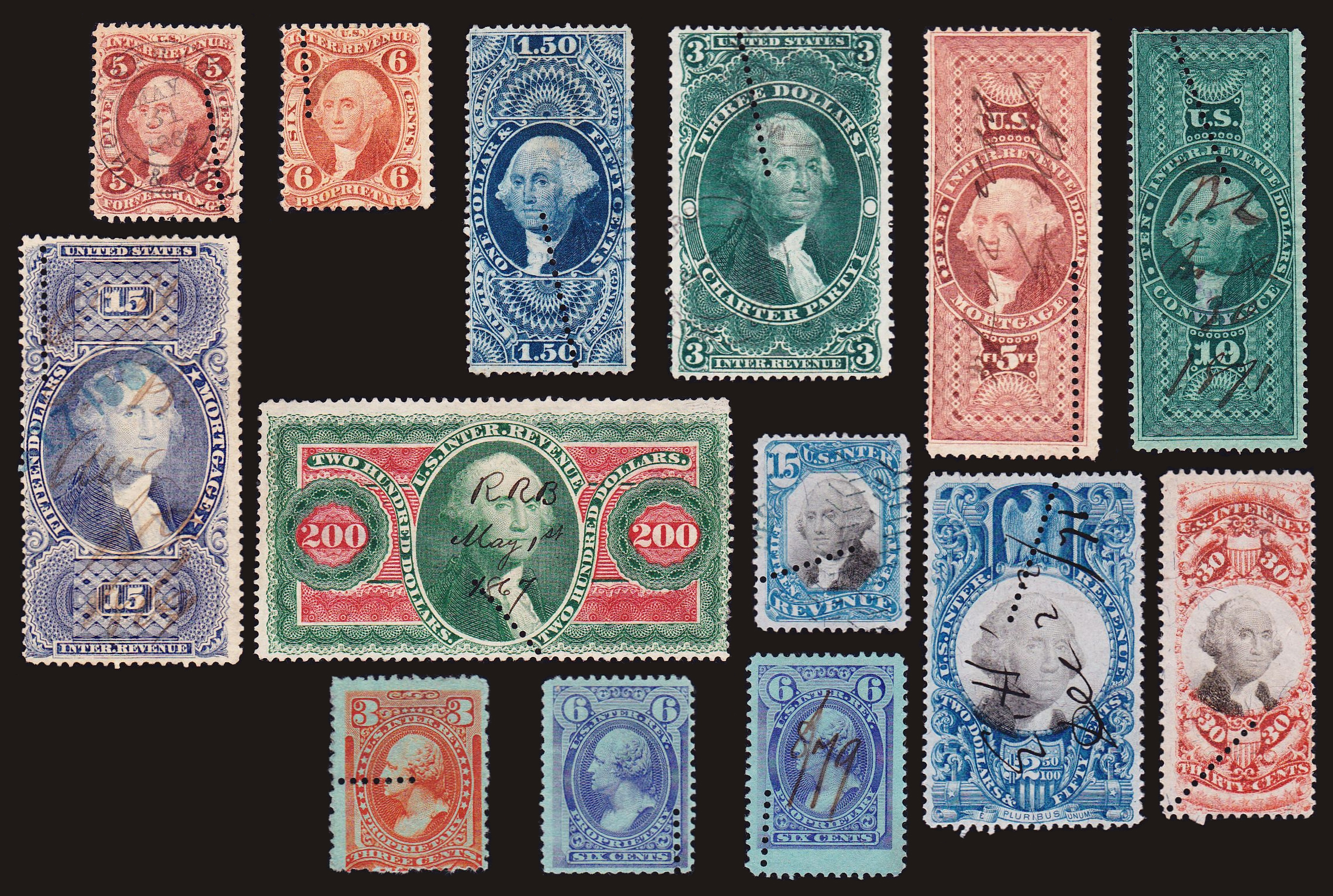
Figure 12. Partial row perforations in the collection made by stroke perforation.
The holes generally have a sharply cut appearance, and the 3c proprietary especially shows the contrast of these with the rougher edge perforations. There is a large range of placements of the partial rows, in contrast to most partial rows of original perforations, which are discussed next.
Figure 13 shows example revenue stamps with partial rows that are original perforation errors. Partial row perforations have largely been regarded with suspicion according to Brett (1990), but Mahler (1991b) produced examples on document which lent credibility to the idea that partial rows can be extra original perforations. Such rows should be produced by halting a rotary perforator upon noticing an operating error such as sheet misalignment or the realization that the sheet had already been perforated, as was suggested by Mahler. Additionally, they could conceivably result from a folded sheet of stamps. Worth noting is that most of these partial rows are nearly parallel to the edge perforations. The blocks #3 and #4 shown in Figure 13 are consistent with an aborted perforating operation; the partial rows are slightly angled, the hole-to-hole spacings of adjacent rows do not correlate with each other or with the fraudulent added perforations, and the partial rows are parallel to each other with a separation consistent with rotary perforation. The upper two partial rows in block #3 are one hole shorter due to an incomplete hole cut that was not punched out. The partial rows in the two blocks are nearly the same length and it appears that the two blocks mate to form a 5 x 2 block.
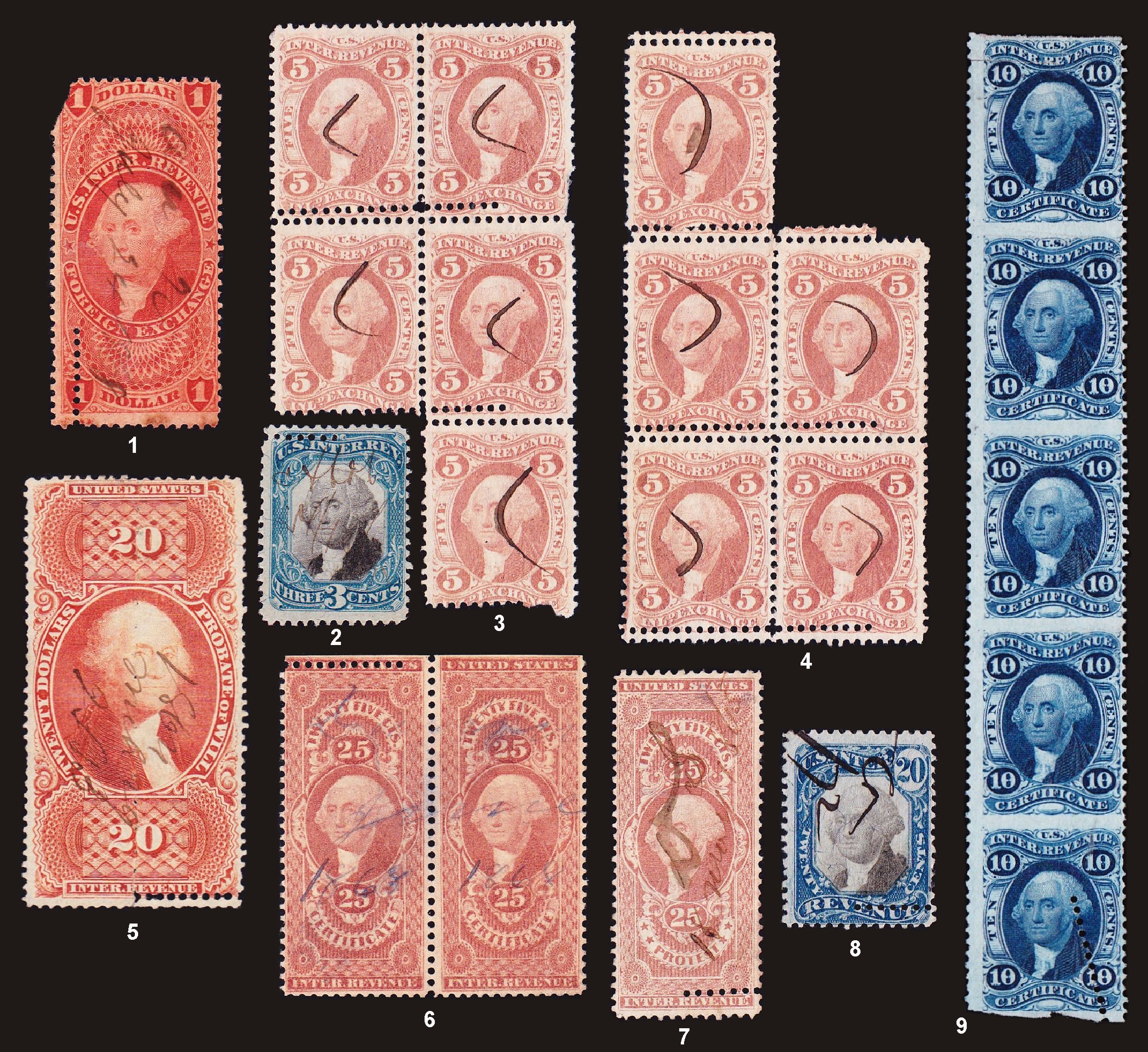
Figure 13. Partial row perforations that are original perforation errors.
The perforation hole sizes in Figure 13 mostly pass the simple test with a gauge. When put to the simple test using the Kiusalas 12-66 holes on the U.S. Specialty Multi-Gauge, most of the holes exhibit visually larger holes than the 0.488 mm hole radius on the gauge. This suggests they are original perforations. The measured average radii of the partial rows in mm are: 0.498 (#1); 0.485 (#2); 0.497-0.504 (#3 and #4); 0.533 (#5); 0.505 (#6); 0.487 (#7); 0.490 (#8); and 0.536 (#9). The hole fit errors for the three which do not pass the radius size test alone are: 10.3 (#7); 12.0 (#2); and 8.9 (#8). Visual examination of Figure 13 shows that the partial rows in stamps #7 and #8 look smooth and round, while stamp #2 shows obvious irregularity of hole shape. Stamps #7 and #8 are simply too close to the cluster of the added perforations shown in Figure 8 to be discerned using this simple visual test with a gauge.
Part-Perfs and Dubious Doubles
No part-perf revenues have been found so far with extra perforations that correlate with the fraudulent added perforations. Especially interesting is the angled, partial row in the scarce strip of five R33b (Figure 13, #9) that appears to be original perforation. While a lack of correlation to the added perforations does not conclusively prove that a row of perforations is original, no other meaningful groups of fingerprints have been found in this comprehensive study and the average hole radius (0.536 mm) is much greater than the largest hole radius of the added perforations that have been observed. In the absence of any indications to the contrary, it appears that the perforations are original. Indeed, expert opinion on the certification for this item termed the extra perforations a “freak partial row.” This is acceptable since “freak” is synonymous with original perforation.
A number of original-appearing extra perforations were produced by stroke perforation. These were likely intended to mimic “double perforation” errors which were common in the first revenue issue. Some examples of these are shown in Figure 14. All of these examples have extra perforations which appear approximately parallel to and near an edge of the stamp. There are a number of stamps such as the example in Figure 2 which have perforations on opposite sides of the stamp with a spacing between the rows that is smaller than the rotary perforator’s wheel separation. An original perforation error with the rotary perforator should result in a new set of rows all displaced to the left or right of the original rows (as in the blocks shown in Figure 13) rather than opposite directions on the same stamp (as shown in Figure 2). Applying the simple test with the transparent specialist gauge, all of the extra perforations in Figure 14 appear to be the same size or smaller than the 12-66 gauge and have holes with round appearance and smooth edges. This is in agreement with the actual measurements of the radii. This research supports the idea that multiple extra perforations on the same stamp are usually added perforations.
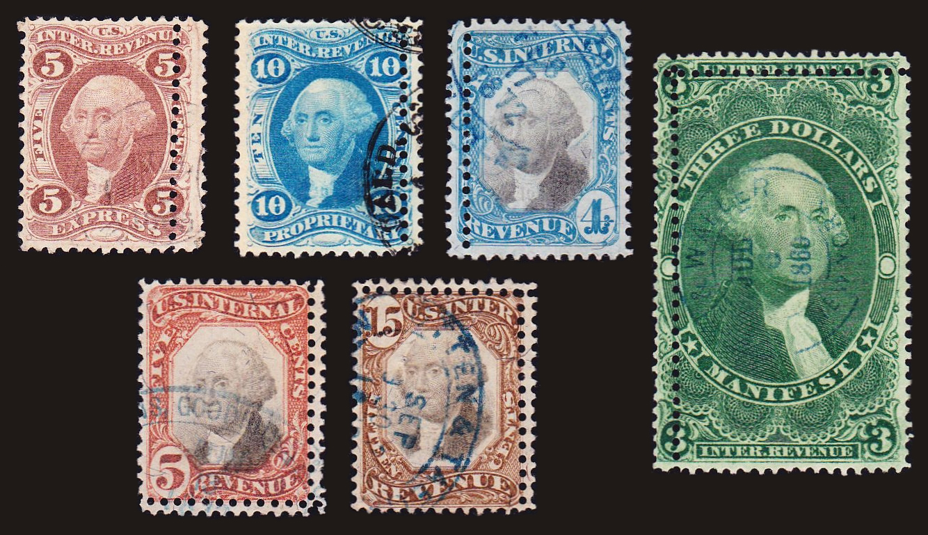
Figure 14. Original-appearing extra perforations that were produced by a stroke perforator.
There is only a single example in the collection with a pair of original extra perforations at adjacent sides (on stamp #2 in Figure 1). It seems that accidental rotary re-perforation in both directions was an infrequent occurrence.
Added and Extra Perforations on a Single Stamp
There are two examples of stamps in the collection having multiple extra perforations in which one row is original and the other is added. Stamps #1 and #7 in Figure 1 both have an original perforation on the left and an added vertical perforation through the interior. When put to the simple test using the transparent 12-66 specialty gauge, the two rows on stamp #1 visually differentiate easily in that the double row has much larger holes. The average actual hole radii for the two rows are 0.505 mm and 0.480 mm for the double and interior rows, respectively. The same visual test put to stamp #7 fails even though the average hole radius in the original row is a considerable 0.015 mm greater. In this case the measured average hole radii are 0.493 mm and 0.478 mm for the double and interior rows, respectively. Unfortunately, the 0.493 mm value is just too close to the 0.488 mm radius of the gauge dots on the transparent gauge for this simple test to work in this case.
Conclusion
Interestingly, no stamps matching the added perforations have been found that are later than the 1880s issues included in this study. While stamps of later issues do occasionally turn up with extra perforations, none have so far exhibited similar fingerprints characteristics to the added perforations on these revenue stamps. This is consistent with the possibility that the production of the added perforations was confined to a single episode carried out by a single individual in the late 1880s with a focus on revenue stamps.
The new analysis methods developed in this research should have additional valuable applications to subjects such as: re-perforation of stamps, including the Washington-Franklins; fingerprint characterizations of other equipment such as different types of comb perforators and harrow perforators; and distinguishing the perforated stamps produced by different companies, whether private or under contract to the government. Preliminary testing also shows that it is possible to fingerprint the perforations of stamps on document using these methods. Viewing the history of fakery as an “arms race” of forgers against authenticators, this research illuminates new paths of “quantitative philately” that can make fraudulent efforts an ever more difficult undertaking.
Quiz Answers for Figure 1
The following stamps have extra perforations that are original: 2, 3, 9, 11, 13, 16, and 19. The following have fraudulent extra perforations: 4, 5, 6, 8, 10, 12, 14, 15, 17, and 18. Two of the stamps each have one extra original perforation and one extra fraudulent perforation: 1 and 7.
Appendix I. Graphical Networks of Original and Added Perforations
The graphical network of perforation patterns in the Second Issue revenues is shown in Figure A-1. The dots representing perforation rows follow the same color coding as used in Figure 9 for the first issues network. The dots are labeled by Scott number, except for edges which are unlabeled to reduce clutter in the graph. The lines represent high correlation scores of 50 or greater. Using a correlation score of at least 50 simplified this graph by showing a smaller number of only very strong correlations; including strong scores of 30 or more causes the graph’s center to become overly dense. In a few cases where a fingerprint for an interior row had scores less than 50, then correlation scores of at least 30 were included and are indicated by dashed lines. The lines only serve to show strong pattern matches, and their length has no significance. Dots without connecting lines represent perforation rows for which strong correlations were not found. In Figure A-1, more than 60 edge perforation rows (black dots) lacked strong correlations and were not included in the graph to reduce clutter. The few correlations that occur with edges appear to be random and mostly with other edges. Compared to the network of patterns for the First Issue revenues, there are few original double or partial perforations.
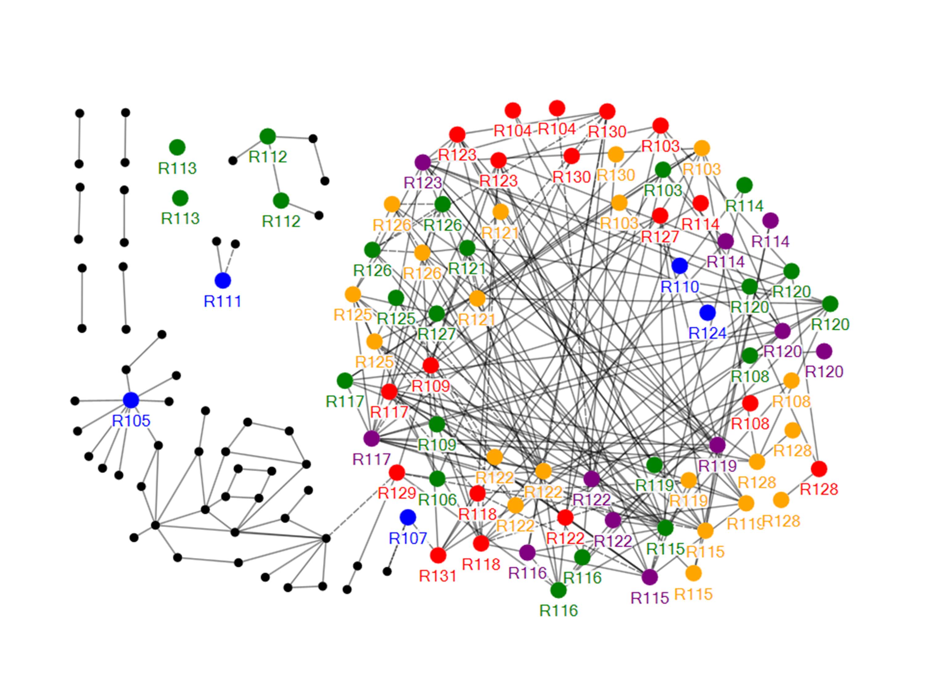
Figure A- 1. Graphical network of matching perforation patterns for the second issue revenues. The findings are very similar to the network shown in Figure 9 for the first issue revenues, but with few original double perforation errors.
There is only a single example in the collection with a pair of original extra perforations at adjacent sides (on stamp #2 in Figure 1). It seems that accidental rotary re-perforation in both directions was an infrequent occurrence.
The Harel-Koren analysis (Harel and Koren, 2002) separates graphical networks into regions of greater and lesser interconnectivity. Highly linked subgroups that are weakly linked to the rest of the perforation fingerprints can be separated and identified in this process. The Harel-Koren analysis applied to all of the added perforation fingerprints (forwards and backwards) in the collection results in a clear separation into two groups as shown in Figure A-2. The forward fingerprints mostly separate from the backward fingerprints resulting in two groups that are mirror images of each other. Thus, the added perforations consist only of a single interconnected group.
There is a small degree of interconnectivity between the two groups which corresponds to the pattern matches with reversed sequences; this is the result of scanning decisions that I made in creating the study database – there are instances where I scanned opposite sides of a stamp in the same direction, when instead the stamps were rotated to bring each edge to the stroke perforator, or I rotated a stamp in the opposite direction for scanning than it was rotated for punching the added perforations. An example of this was discussed and presented in Figure 8.
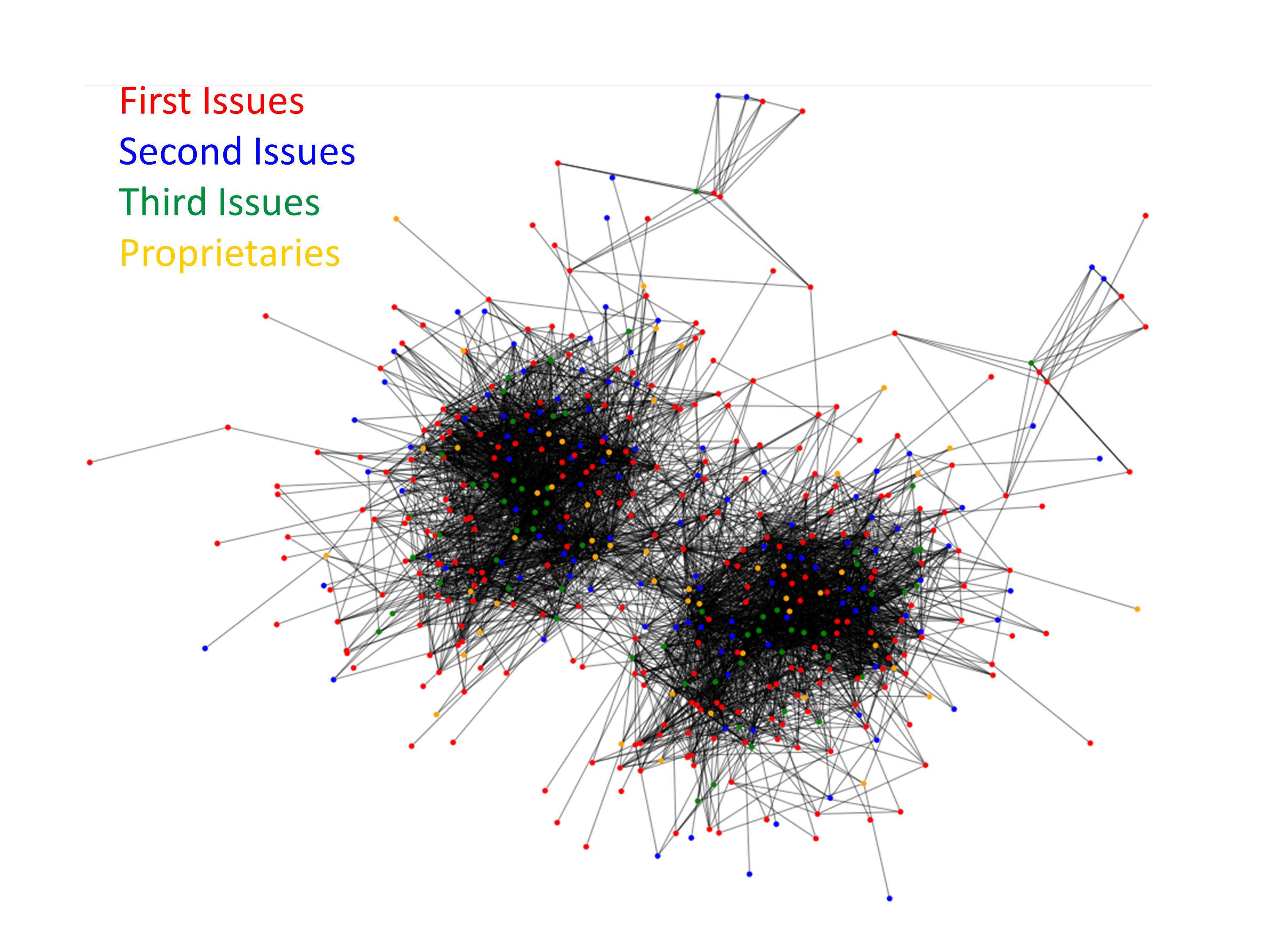
Figure A-2. Analysis showing that all of the correlated perforation patterns (including all sequences both forwards and backwards) from the first three issues and the proprietaries separate into a single group (forwards) and its mirror image (backwards). There are no other groups of significant size found.
Appendix II. Edward B. Sterling’s Enumeration of Rarities and Their Valuations in His Revenue Catalogue of 1888
Edward B. Sterling assembled a very comprehensive collection of revenue stamps before publishing his series of Sterling’s Standard Descriptive and Price Catalogue of the Revenue Stamps of the United States. The fifth edition of 1888 became a standard reference work for U.S. revenues. In that same year he sold his pioneering collection to Hiram Deats for $7000, an enormous price for revenue stamps in that time. He later acquired the records and archives of Butler and Carpenter, a producer of both private and government revenue stamps for the U.S. Treasury Department. This material he also sold to Deats.
Sterling’s 1888 revenue catalogue describes more than 4,000 varieties of revenue stamps including perforation varieties, pre-print paper folds, paper varieties, imprints, and imperforate multiples. His catalogue includes 330 descriptions of specific revenues having extra perforations, and his descriptions nearly all conform to the extra perforations found to be original in this study. More than 90% of his descriptions are for double perforations, with the remainder being mostly partial row perforations along an edge of the stamp. His catalogue includes only one first issue revenue with double perforations on two adjacent sides (a different stamp from Figure 1, #2). There are only 3 interior perforation rows described in his catalogue for the first issue stamps. Two of these consist of a vertical row through the centers of the stamps, while the other has a diagonal row near the top. There are six partial rows in the first issues that are described as going toward the center of the stamp. There is only a single description of a stamp with crossing interior perforations in his catalogue. This was observed on a multiple of a private die match stamp.
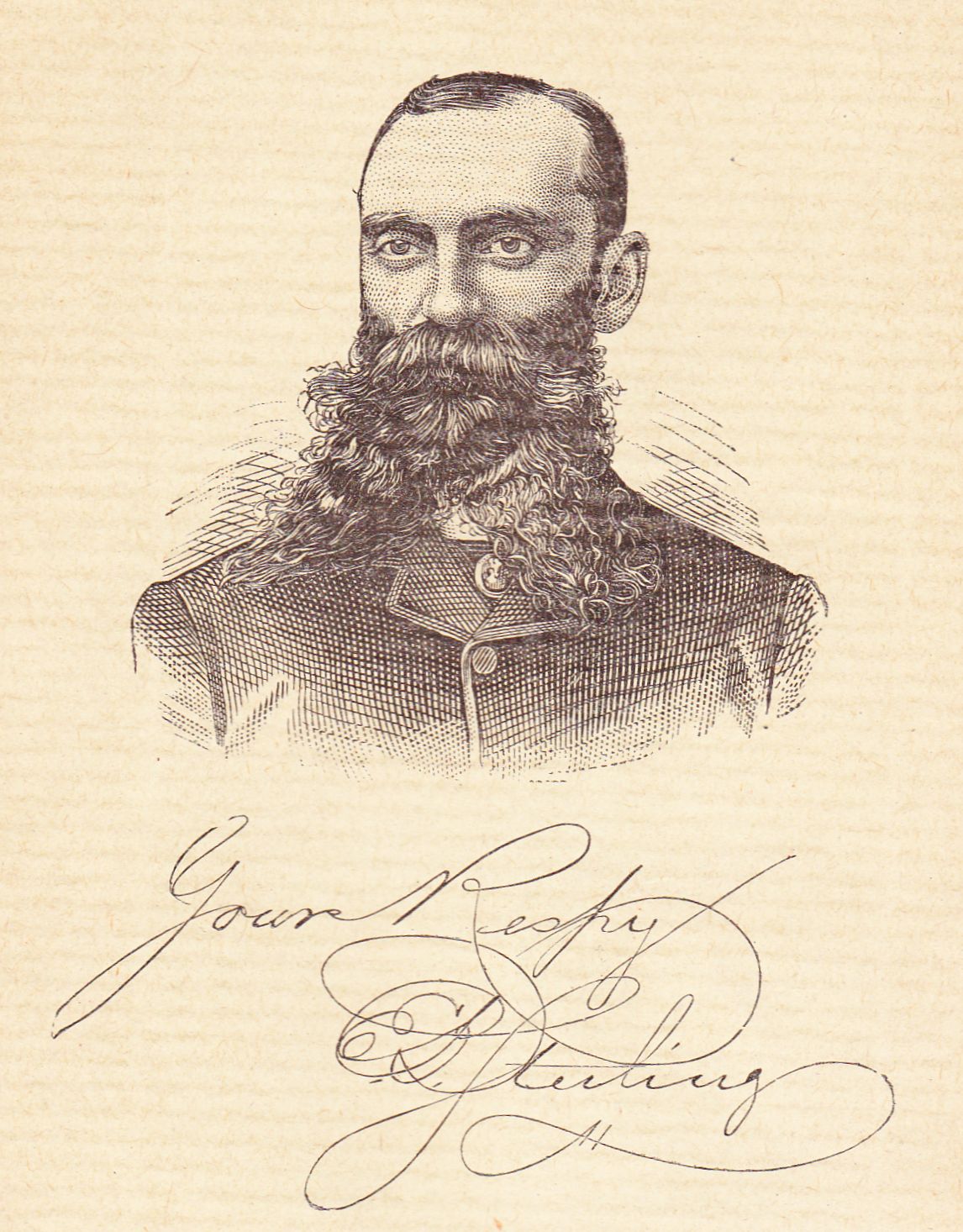
Figure A-3. Pioneer revenue collector, Edward B. Sterling, pictured in his Sterling’s Standard Descriptive and Price Catalogue of the Revenue Stamps of the United States , 5th ed., 1888.
Regarding the later revenue issues, the catalogue reports only 37, 15, and 2 stamps with extra perforations for the 2nd, 3rd, and 4th issues, respectively. This agrees with the steep decrease of original extra perforations in later issues observed in this study.
Considering the extent of Sterling’s collection, the rare observance of interior perforation rows crossing the stamps, and the extensive consistency of his descriptions with original perforation errors, it appears that Sterling’s collection may have been one of the best surveys of revenue stamps before stamps with fraudulent extra perforations were introduced to the stamp market. Given the extent of his collecting, he was in a good position to attach valuations to perforation errors before the authenticity of these stamps came into doubt. While his prices of $0.25 to $0.50 for many of these perforation errors may seem like high multiples, this is similar to current valuation practices for rare varieties, especially for stamps otherwise having “penny” valuations.
Appendix III. Technical Description of the Analysis Methods
High resolution images were obtained with a Canon 9000F flat-bed scanner used in positive monochrome film mode. The method of scanning creates a dark image of the stamp with white holes. This mode uses an insert which limits images to a width of about 57 mm. Images were investigated using resolutions from 600 dpi to 9600 dpi to determine the appropriate resolution for this research. A resolution of 2400 dpi was found to provide sufficiently high resolution without burdening the analysis with overly large file sizes and excessive computation times. All scans were done with the stamps placed directly on the platen, and small weights away from the features of interest were placed on the stamps if there was any observed curvature or lift of the stamps above the platen. All scanning of perforation rows was done by orienting the rows horizontally in the scanner. The scanned image of a 40 mm transparent ruler on a Stanley Gibbons Instanta gauge measured 39.994 mm in pixels for an estimated error of only 0.01%. Similar tests with 1 mm sized objects gave close agreement between micrometer measurements to the nearest 0.0001 inch and the image width in pixels. Vertical orientation in the scanner gave a much larger error. Images were manually processed using Adobe Photoshop software and then analyzed using computer programs written in Free Pascal (Free Pascal team, 2013). The Photoshop manipulations were as follows: Images were converted to gray scale; the ‘trace contour’ feature was used to determine a 1 pixel-wide contour of the holes in the image; the image was cropped down to just the row of holes of interest; and the ‘brush’ tool was used to eliminate any remaining parts of the image other than the hole contours. From the ‘Levels’ tool, the midpoint between the highest black peak and the white peak (typically about 155) is used for the ‘trace contours’ level with the low bias setting. The measured radius of a hole feature can be corrected by a factor of r/(r-0.5), where the value of the radius, r, is in pixels, to compensate for the use of a 1 pixel-wide contour. The ‘trace contours’ feature provided superior results to the more standard ‘find edges’ feature (2 pixel-wide contour) because of the better defined, more constrained hole edge. The ‘trace contours’ method with the applied correction was compared with the ‘find edges’ method in processing a perfect circle of 1 mm diameter created in software at different resolutions. Both methods were found to converge to the exact radius with increasing resolution of the image, and at 2400 dpi the ‘trace contours’ method was within 0.3 microns of the correct result for the radius. The brush tool was used to erase the bridges between the holes at the edges of the stamps so that the only remaining parts of the image were the data arcs of the holes to be fitted with circles.
The measurement of circular arcs in digital images is a widely encountered application in physics (Chernov, 2010). Partial arcs of data are particularly prone to varying degrees of error depending upon the method. Several methods were evaluated for this application, with special focus on their ability to correctly fit the partial arcs from edge images of stamps. Methods tested included Nelder-Mead “simplex” iteration (Nelder, 1965), Levenberg-Marquardt iteration (Levenberg, 1944), and the linear least squares approach adapted to circular data by Coope (Coope, 1993). Test images were created with scans of real perforations and a two-step process was used to apply these methods. First, a low resolution search with a circular mask of 0.49 mm radius was performed by scanning the perforation row image. When circular arc data was found that overlapped the mask, this location was then used to launch one of the circle fitting methods for the second step of the process.
A large number of studies at different resolutions compared these methods using real image data having a range of arc lengths. The Nelder-Mead method was unreliably sensitive to the initial estimates used to launch the method, while the matrix algebra methods of Levenberg-Marquardt and Coope were both very fast and in near agreement. The Coope method performed slightly better in the testing with partial arcs of data encountered with edge images, and was adopted for the second stage, high resolution analysis.
The minimum arc lengths for typical edge perforation images were about 145 degrees of arc, and the methods work well down to about 120 degrees. Below this arc length the methods deviated towards larger values of the radius. In edges with badly worn or rounded-off bridges between perforations, the short arcs thus tend toward overly large fitted circle sizes. The data in Figure 8 shows a large assortment of double perforation errors (green) that are measured over 360 degrees of arc length. The radius of the original perforations is generally less than 0.525 mm. For this reason, if the Coope analysis returned a radius in excess of 0.535 mm, a cross correlation of the image at high resolution using a 0.535mm radius mask was instead used for the second step of the circle fitting process. The 0.535 mm radius gives a sensible maximum radius value for 12-66 perforation of these stamps, and avoids introducing a grossly offset hole center from an erroneous fit to a short or rounded-off data arc in an edge row.
The fitting of a circle to the image determines the radius of the circle and the coordinates of circle location in the image. Using an estimate for the perforation gauge, the computer program searched for the next arc of data in the row of perforations. This process is simply repeated until the right edge of the image is reached.
After a circle is fit to an arc of data, a calculation can be made for the error of the fit. This was defined as the average intensity-weighted root mean square error in the radius calculated for all of the image in the neighborhood of circle. This ‘hole fit error’ was scaled to the number of data points so that the result is independent of the length of the data arc. Better fits of circles to the hole outlines result in lower error values. Increased hole fit error can come from at least two sources: non-circular shape and roughness of the edge contour in the image. Rough, torn, or fibrous edges on perforations will result in irregular edge contours and increase the hole fit error. Partially punched perforations also will result in increased error, and if grossly misshapen will introduce error to the circle fit as well. For this reason, portions of data arcs that are not representative of the perforation row due to defects such as tears, unremoved paper in partial punches, etc. are deleted from the image to prevent skewing of the average results. Two examples of hole fit error are shown in Figure A-4 and Figure A-5. Figure A-4 shows an example of a pair of adjacent holes in a rough appearing double perforation error of a Scott #R27 having high values of the hole fit error. The 1 pixel-wide contour from the actual image is shown in green. The initial estimate of the hole center is shown by a red cross mark and the center of the fitted circle is shown by a green cross mark. The numbers below the center marks are the fitted radius in microns and the hole fit error. Figure A-5 shows the much smaller error with the rounder, more regular holes obtained from an image of the added perforations on a Scott #R135. The video graphics images in the two figures are generated using rounded-off, integer values for radius and screen position, but the actual numerical results are far more accurate.
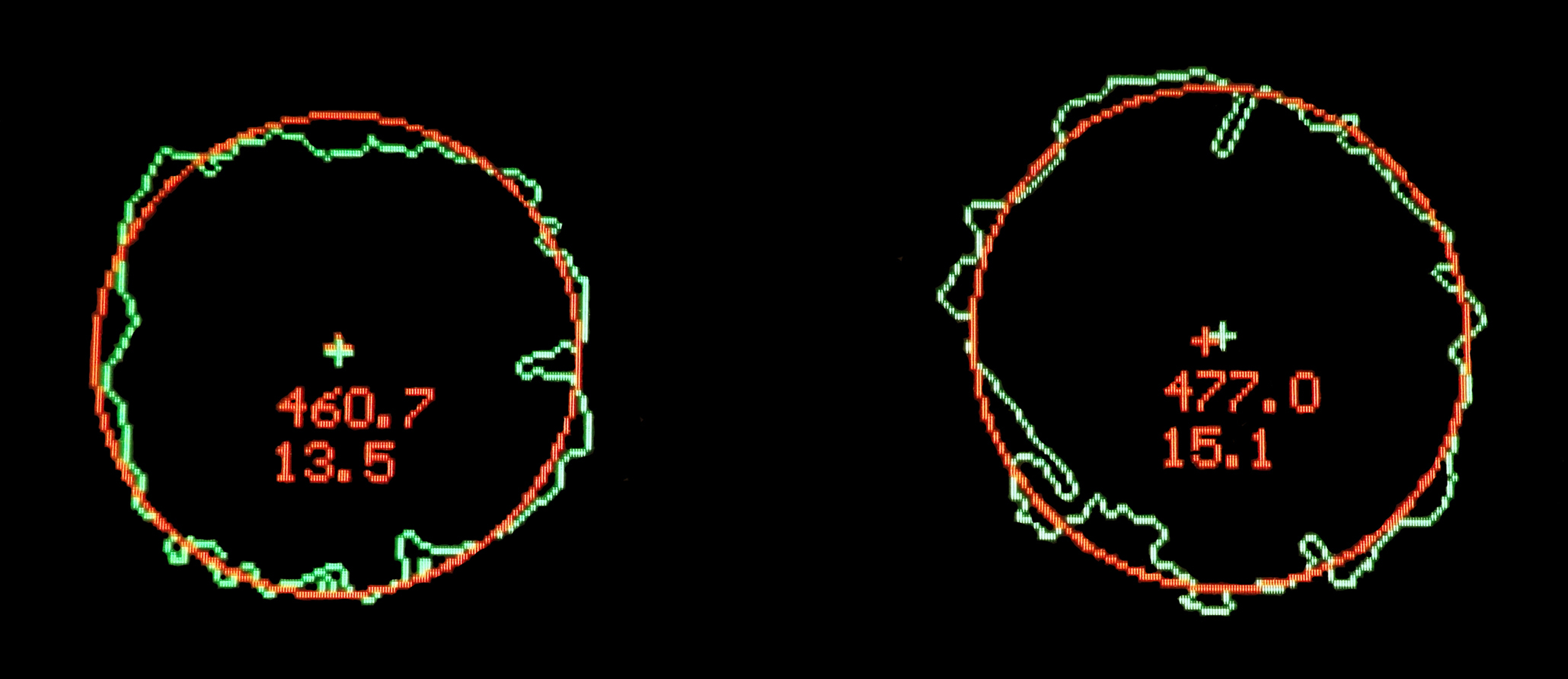
Figure A-4. Two adjacent holes from an original perforation error of Scott #R27 from an image displaying rough hole contours. The 1-pixel wide contour line showing the hole edge from the processed image is shown in green. The best circle fit is shown in red and the radius (in thousandths of a mm, or microns) is the top number. The lower number is the hole fit error.
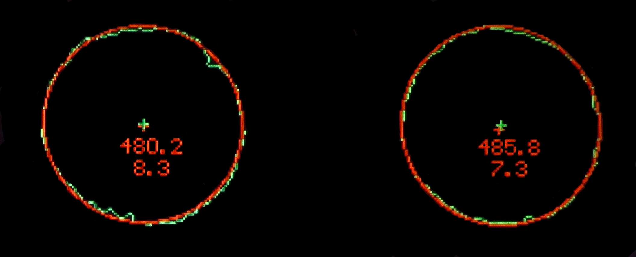
Figure A-5. Two adjacent holes from added fraudulent perforations of Scott #R135 showing much smoother, more circular holes and much smaller values for the hole fit error.
After the hole locations in the row are determined, the average perforation gauge and the pattern of hole spacings were calculated. A matrix algebra method determined the gauge by a linear least squares solution of two variables: the horizontal coordinate of the first circle of the gauge, and the average spacing in the gauge to best fit the sequence of perforations. While the scans are done near horizontal in the scanner, any slope in the data is removed by first doing a linear least squares analysis of the hole center positions. Given the micron level accuracy of the circle fitting methods, the gauge measurements vary less than 0.01 of a gauge unit upon repositioning the stamp in the scanner and rescanning. This is a resolution that is more than 20 times smaller than the normal variation in gauge encountered with these stamps.
Files were generated containing analysis results for each perforation row included the sequence of center coordinates, hole radii, hole fit errors, and distances between consecutive centers. The cross correlation of a pair of perforation rows was done by deter-mining the alignment that best matched the patterns. All possible alignments were evaluated by translating one sequence over the full length of the other, and the differences between the sequences were squared and summed giving a measure of the variance. In seeking the overlap with the least variance, it is important to not allow trivial situations involving coincidental overlapping of one or two values at the ends of the two sequences. Therefore, a ‘score’ was developed to scale the correlation result by the length of the actual overlap. The correlation score was expressed as 10-3n/variance, where n is the length of the overlapping region of the sequences and the variance is the sum of the squares of the errors using hole spacings in mm. Further, overlaps of less than 8 values or less than the shortest row length were not allowed. The median value of computed scores in the approximately two million correlation studies resulting from 2,000 different hole sequences was approximately 0.3. The graphical networks in Figures 9 and A-1 utilized results having minimum scores of 50, very large correlation scores that are visually evident in the close pattern matches shown in Figures 2-5.
NodeXL (The Social Media Research Foundation 2013), a template for Microsoft Excel, was used for creating the graphical networks shown in Figures 9 and A-1. The circular graphical layout option of NodeXL was manually edited to group perforation rows from the same stamp in the network graph. Redundant reverse correlations were manually deleted from the graphs. The Harel-Koren Multiscale analysis (Harel and Koren 2002) for sorting nodes according to the degree of interconnectivity is a feature in the NodeXL template.
The reconstruction of a hypothetical stroke perforator’s pin sequence was accomplished using a program that worked through a listing of all of the correlation scores starting with the highest values. The matches would determine a common sequence for the pin spacings. After the first pairing based on the highest correlation score, a third pattern sequence was overlaid with the pin pattern based on the highest correlation to either of the first two sequences, and so forth. In the course of this process, the ends of new pin sequences would sometimes extend beyond the existing selections and further increase the number of pins in the hypothetical perforator.
References
Brett, G. W. Some Aberrant 19th Century U.S. Revenue Stamp Perforations. The American Revenuer, 1990 September; 44: 163-172.
Chernov, N. Circular and Linear Regression: Fitting Circles and Lines by Least Squares. Chapman & Hall, CRC Monographs on Statistics & Applied Probability, CRC Press, Taylor & Francis, NY, 2010.
Coope, I. Circle Fitting by Linear and Nonlinear Least Squares. J. Optimization Theory and Applications, 1993; 76:381-388.
Free Pascal team, Free Pascal open source compiler project, www.freepascal.org, 2013, version 2.6.2.
Harel, D. and Koren, Y. A Fast Multi-Scale Method for Drawing Large Graphs. J. Graph Algorithms and Applications 6:3 (2002), 179-202.
Leavy, J. B. Fake Perforations. The Philatelic Gazette, 1918 May; 154-155.
Levenberg, K. A Method for the Solution of Certain Non-Linear Problems in Least Squares. Quarterly of Applied Mathematics 1944; 2:164–168.
Mahler, M. Diagonal Perfs on Document. The American Revenuer, 1991a January; 45: 16-17.
Mahler, M. Extraneous Perfs on Document. The American Revenuer, 1991b February; 45: 35-38.
Mahler, M. Extraneous Diagonal Perfs on Document. The American Revenuer, 1991c June; 45: 120-122.
Nast, C. A. Freak Perforations. Carter’s Messenger, 1908; 1:74-75.
Nelder, J., and Mead, R. A Simplex Method for Function Minimization. Computer Journal, 1965; 7: 308–313.
The Social Media Research Foundation, www.nodexl.codeplex.com, NodeXL Excel Template, version 1.0.1.245, released June 19, 2013.
Sonic Imagery Labs, Castro Valley, CA, Precision U.S. Specialty Multi-Gauge, Revision 5.1, 2013.
U.S. Bureau of Printing & Engraving, U.S. Dept. of the Treasury, 2013, reprinted private communication dated July 4, 1964, original recipient redacted.